Wang Hao, Sun Junfeng, Kasike Signal Co., Ltd.
Keywords: IPMI, security computer, temperature sensor, voltage sensor
In the system design, to consider the use of derating design and other measures in order to improve the reliability of the use of components and prolong the life of the product, the design methods that consider the stress of electricity, heat, etc. are listed as follows: 1 For devices with large heat generation, the most The commonly used method is to install a radiator (using water-cooled, air-cooled, etc.); 2 pairs of over-voltage protection, usually choose high voltage withstand devices and design some overvoltage protection circuit.
For safety electronic systems, the above design is not enough. According to the EN 50129 standard, temperature and voltage monitoring circuits must be designed. Because in some special cases, dangerous output may occur when the temperature or voltage exceeds the threshold range without completely damaging the device. These specific conditions may be one of the following: 1 heat accumulation due to accumulated dust or cooling fan damage, aging (oxidation) of the heat-dissipating components, and poor contact of the heat-dissipating surfaces. 2 The output voltage increases or decreases due to aging of the power supply voltage regulator or aging or failure of the voltage adjustment resistor. As shown in Figure 1, when the LT1185 regulator ages or fails due to aging drift or the voltage regulator resistor R1 or R2, the output voltage may be too high or too low.
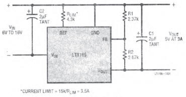
Figure 1 voltage regulator circuit
1 Introduction to IPMI
For an organization with a large number of host systems, monitoring 24-3 hours or more of host operations in 24 hours is a huge project. Therefore, in 1998, Intel, DELL, HP, and NEC jointly proposed the IPMI 1.0 (Intelligent PIatform Management Interface) specification. As part of the DMTF15 standard, it provides a cross-platform standard to regulate the health of various hardware in the system. Conditions such as CPU operation, fan speed, system temperature, and voltage. Under different processors, different BIOS, operating system. All can provide the function of identifying information, monitoring, running and restoring records. The administrator can set the critical value for the part to be monitored. When the IPMI controller detects an abnormal condition, it can notify the system management by sending an E-mail, SNMP (Simple Network Management Protocol) Trap, a light signal, or a buzzer sound. Deal with problems. The latest standard is IPMI 2.0. As shown in the IPMI management platform architecture diagram in Figure 2, the IPMI information is communicated through the Baseboard Management Controller (BMC).
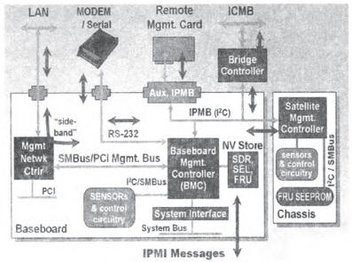
Figure 2 shows the architecture of the IPMI management platform
2 system design
This board selects a manufacturer's COTS product, as shown in Figure 3 for the board IPMI module a brief diagram, Renesas 16-bit microcontroller H8S for the board lPMI core functional unit, responsible for the temperature sensor data, voltage sensor data collection And event records. The Freescale MPC8572 is the core computing CPU of the board. It communicates with the H8S microcontroller through the I2C bus. The communication protocol format standard follows the IPMI 1.5 standard. In addition to this, the microcontroller H8S can communicate with the remote management system through two IPMB buses (the CPCI backplane connectors P1 and P2 provide external connections).
As shown in Figure 3, ADT7461 is a single-channel temperature monitor with an operating voltage of 3 to 5.5V. A digital temperature sensor for the 0°C to 127°C range that automatically compensates for the 1000, Q parasitic resistance generated by the sensor and recording circuit. The measurement process calculates the correct temperature value by switching the current source and comparing the output voltage. The sensor measurement accuracy is 1 °C, the entire measurement process can be through the SMBus (SMBus is the abbreviation of the System Management Bus, it is mostly based on the I2C bus specification. Like I2C, SMBus does not need to add an extra pin) for remote setting.

Fig. 3 Schematic diagram of the IPMI interface of the safety logic board
3 Temperature and Voltage Driven Software Development
The board manufacturer only provides the IPMI communication protocol message interface function, does not provide temperature, voltage drive interface, and needs to be developed by itself. According to the IPM1 message standard, when sending a data request message to a BMC controller, a network function number (NET FUNC), a request logical unit number (RSLUN), a request command, and request message data of the request message should be provided. According to the manufacturer's card user development manual, part of the IPMI message request for the voltage and temperature data request is as follows:
1) Temperature sensor data request message:
reqMsg.netFn=IPMI_NETFN_APPLIC;/* indicates that the network function number is an application message request*/
reqMsg.rsLun=0; /*Local request*/
reqMsg.command=IPMI_APPLIC_CMD_MSTR_WR_RD_I2C;/*Read and write I2C commands*/
reqMsg.pReqData[0]=(Busld<<1)| 0x1;/*0x1 indicates private bus*/
reqMsg.pReqData[0]=I2C_Channel <<4;/*I2C_Channel is the FC channel number*/
reqMsg.pReqData[1]=DevAddr; /*The address of the temperature sensor on the I2C bus*/
2) Voltage Sensing Data Request Message:
reqMsg.netFn=IPMI_NETFN_SENSOR;/* indicates that the network function number is a sensor data request*/
reqMsg.rsLun=0;/*Local request*/
reqMsg.command=IPMI_SENSOR_CMD_GET_READING;/*Read sensor data command*/
reqMsg.pReqData[0]=Sensor_ID;/*voltage sensor ID number*/
Because the voltage sensor sampling data is discrete, it can not directly express the voltage floating point value (such as 1-2V, 1.8V, etc.), it needs to convert the discrete value into floating point value, according to the IPMI 1.5 standard nonlinear sensor sampling data conversion formula :
The parameters in formula (1) are described as follows:
X-discrete data; y-transformation data; L[]-linear values; M-signed constants multiples; B-signed offsets; K1-signed exponents; K2-signed result exponents.
These parameters need to read the “sensor read factor†command. The format of this command data message is shown in Figure 4.

Figure 4 Sensor Read Factor Message
The corresponding message request code for this section is as follows:
reqMsg.netFn=IPMI_NETFN_SENSOR;/* indicates that the network function number is a sensor data request*/
reqMsg.rsLun=0;
reqMsg. Command=IPMI_SENSOR_CMD_GET_READING_FACTORS;/*Read sensor factor command*/
reqMsg.pReqData[0]=Sensor_ID;/*voltage sensor ID number*/
reqMsg.pReqData[1]=Reading_Byte;/*Read message word length*/
The prototype of the IPMI communication protocol message interface provided by the manufacturer is as follows:
STATUS syslpmSsifCommand(IPMSSIF_ID ssifld, /*interface descriptor*/
IPMSSIF_REQ_MSG *pReqstMsg, /*the request message to send */
IPMSSIF_RSP_MSG *pRespMsg /*where to put the response message*/
);
The use of this function is very convenient, the interface descriptor uses the system default sysSsifld, the request message and receive message buffer pointers are transferred, you can get the received message. The integrity of the received packet is checked by checking whether the value of the ompletion code field of the received packet is correct, as follows:
If(response compCode != IPMI_COMPCODE_OK)
Return(ERROR);
The data in the data field of the temperature sensor receiving message is a discrete temperature value and can be directly obtained (accuracy is 1°C). The acquired voltage value is somewhat complicated. First, the sensor data command is used to obtain the discrete value, and then the correction factor value in the formula (1) is obtained by requesting the sensor to read the factor command. Finally, the voltage floating point value is obtained by formula calculation.
4 Conclusion
After the development of the drive is completed, combined with the actual application, once the temperature and voltage exceed the specified threshold, the system will be oriented to safety. The drive can accurately obtain real-time temperature and voltage values ​​of the board in a timely manner, and the test scheme is feasible. The disadvantage is that reading the temperature and voltage value is slightly longer (caused by the low I2C bus speed). It needs to be run as a background low-priority task of the real-time operating system. Occasionally, a read error occurs. Rereading it once can solve the problem.
Description
✿Service Life
Mechanical ≥ 1000000cycles
Electrical ≥ 50000cycles(Degree of protection againstDepend on model No.
✿Approvals
UL CUL VDE TUV CE DEMKO CQC
✿ Material
Made of high quality plastic and metal, rust resistance and corrosion resistance, durable enough for you to hanging items, So the product appearance is exquisite, perfect workmanship.
✿ Rating
You can meet the different RATING daily needs. Please pay attention to the model of the switch before purchase, to ensure that you purchase the same as you need.
✿ Vairous Sizes
Actuator Action is momentary and Actuator Type is long straight hinge lever. Switch Body Size as shown in the picture.So different sizes can meet all your daily different needs.
✿ Wide Application
Home appliance: micro oven, electric cooker, washing machine, electric heater, warmer, water fountain and so on.
Commercial appliance: Vending machine, electric toy, electric tools, duplicating machine and so on.
Machinery: Transport machinery, printing machinery, textile machinery and so on.
Basic Micro Switch,Micro Power Switch,Waterproof Micro Switch,Micro Switch Limit Switch
Ningbo Jialin Electronics Co.,Ltd , https://www.donghai-switch.com