1. To measure the forward and reverse resistance of a bidirectional trigger diode, use a multimeter set to R×1k or R×10k range. Normally, both the forward and reverse resistances should be infinite. If the measured values are low or zero, it indicates that the diode is damaged or shorted.
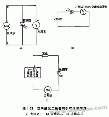
2. Measuring the breakover voltage can be done in three different ways. The first method involves connecting the positive and negative terminals of a megohmmeter to the two ends of the bidirectional trigger diode. This provides the breakdown voltage, which can then be measured using a DC voltmeter. After reversing the polarity of the diode, repeat the measurement and compare the results. A small deviation (typically 3–6V) suggests good performance. The larger the deviation, the worse the diode's performance.
The second method involves measuring the mains voltage (U) with a multimeter. Then, connect the bidirectional trigger diode into the AC voltage measurement loop of the multimeter and apply the mains voltage. Record the voltage reading (U1), then trigger the diode by connecting its two terminals. Measure the new voltage (U2). If U1 and U2 are the same but differ from the original mains voltage (U), it indicates good conduction. A large difference between U1 and U2 suggests asymmetrical conductivity. If U1 and U2 match the mains voltage (U), it means the diode is shorted internally. If both readings are 0V, the diode is open-circuited.
The third method uses a 0–50V adjustable DC power supply. Connect the positive terminal of the power supply to a 20kΩ resistor, and then connect this to one end of the bidirectional trigger diode. The negative terminal of the power supply is connected to a multimeter set to the current range (1mA). This is connected to the other end of the diode. Gradually increase the power supply voltage until the ammeter shows a significant deflection (tens of microamps or more), indicating the diode has turned on. At this point, the power supply voltage value represents the breakover voltage of the diode. Figure 4-73 illustrates this testing method.
Zirconia Ceramics,Zirconia Engineering Components,Zirconia Precision Parts,Zirconia Wear Resistant Parts Yixing Guanming Special Ceramic Technology Co., Ltd , https://www.guanmingceramic.com