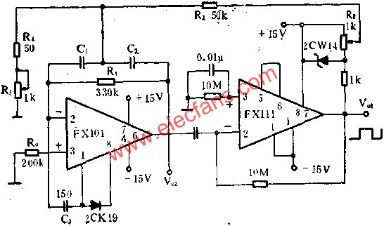
The figure shows a sine wave and rectangular wave generator circuit composed of a high-performance op amp FX101 and a precision voltage comparator FX111. As shown in the figure, the R3 can be changed over a wide range by changing R3. FX111 output ( V01) is a rectangular wave. The FX101 bandpass filter is used. The FX101 output (V02) is a sine wave, R3 (1K) is used to adjust the positive feedback amount, and the Zener diode 2CW14 is used to limit the feedback amount. This article refers to the address: http:// Winnowing Machine,Winnowing Rice,Seed Winnowing Machine,Grain Winnowing Machine Hunan Furui Mechanical and Electrical Equipment Manufacturing Co., Ltd. , https://www.frcornthresher.com