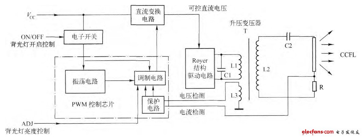
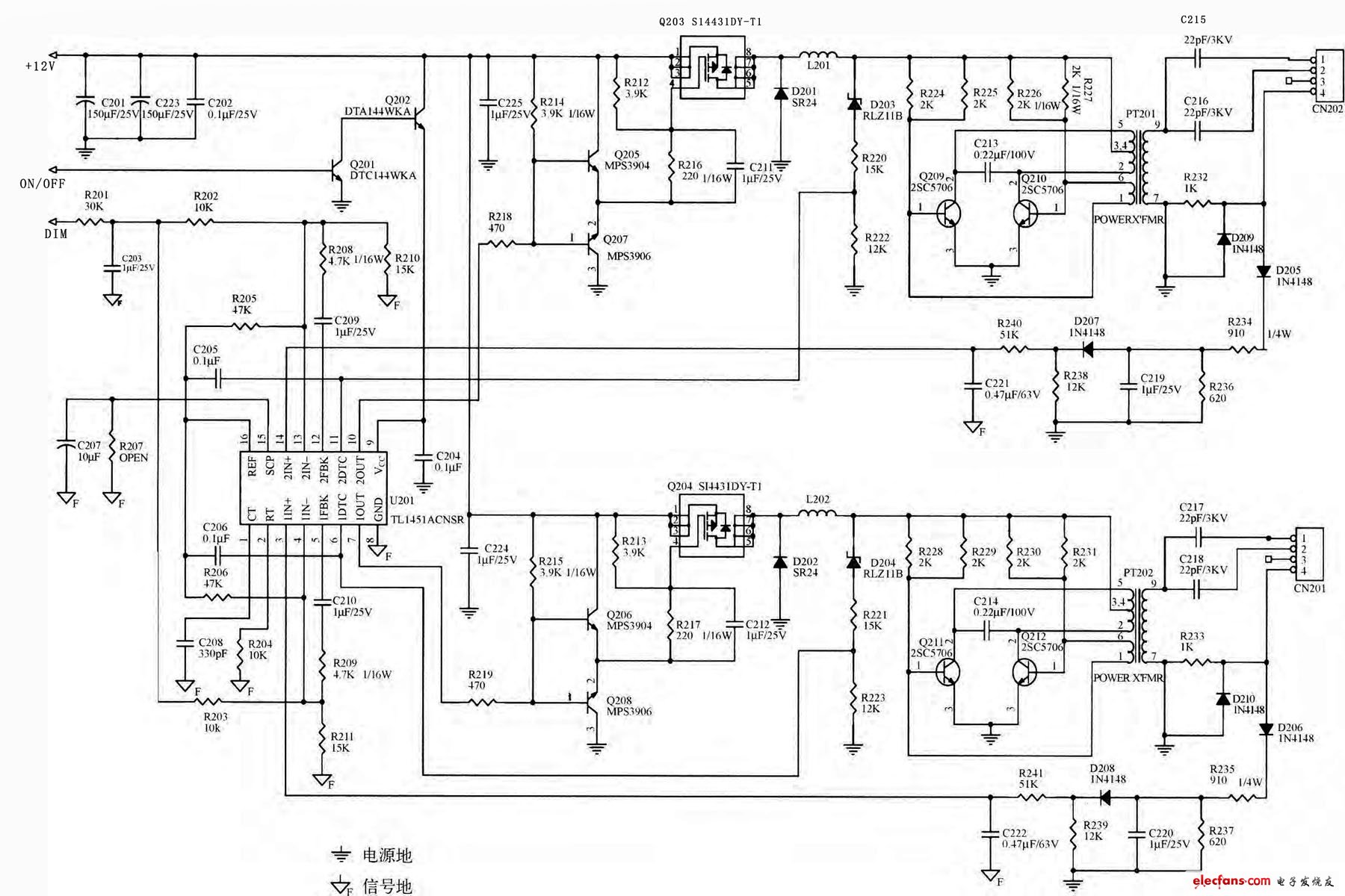
The high voltage board circuit (inverter) is a DC-AC (DC-AC) converter, and its working process is the inverter process of the switching power supply. The function of the switching power supply is to convert the AC voltage of the mains grid into a stable Vcc voltage (12V or 24V), and the high-voltage board circuit is just the opposite. It converts the Vcc voltage (12V or 24V) of the switching power supply output into high frequency ( 40~80kHz) high voltage (600~800V) AC. There are many types of high voltage circuit, and depending on the driving circuit, there are mainly the following components. First, "PWM control chip + Royer structure drive circuit" constitutes a solution 1. The basic structure of the "PWM control chip + Royer structure drive circuit" Figure 1 shows the basic structure of the "PWM control chip + Royer structure drive circuit" configuration. As can be seen from the figure, the high voltage circuit is mainly composed of a drive control circuit (oscillator, modulator), a DC conversion circuit, a Royer structure drive circuit, a voltage and current detection circuit, a CCFL, and the like. In the actual high voltage board, the oscillator, the modulator and the protection circuit are often integrated to form a small integrated circuit, which is generally called a PWM control chip. The ON/OFF in Figure 1 is the oscillator start/stop control signal input. The control signal is from a motherboard microcontroller (MCU). When the LCD color TV changes from the standby state to the normal working state, the MCU sends a start working signal (high/low level change signal) to the oscillator, and the oscillator starts after receiving the signal. Working, generating an oscillating signal with a frequency of 40~80 kHz is sent to the modulator, and after modulating the PWM brightness adjustment signal sent from the MCU part in the modulator, the PWM excitation pulse signal is output and sent to the DC conversion circuit to generate the DC conversion circuit. The controllable DC voltage supplies power to the drive circuit power tube of the Royer structure. The power tube and the peripheral capacitor c1 and the transformer winding L1 (corresponding to the inductor) form a self-oscillating circuit, and the generated oscillating signal is boost-coupled by a power amplification and a step-up transformer, and outputs a high-frequency AC high voltage to illuminate the backlight tube. Figure 1 "PWM control chip + Royer structure drive circuit" constitutes the basic structure of the scheme. In order to protect the lamp, an overcurrent and overvoltage protection circuit is required. The overcurrent protection detection signal is taken from the sampling resistor R connected in series on the backlight tube and sent to the drive control chip. The overvoltage protection detection signal is obtained from L3 and also sent to the drive control chip. When the output voltage and the operating current of the backlight tube are abnormal, the drive control chip controls the modulator to stop output, thereby playing a role of protection. When the brightness is adjusted, the brightness control signal is applied to the driving control chip, and by changing the duty ratio of the PWM pulse outputted by the driving control chip, thereby changing the magnitude of the DC voltage outputted by the DC converter, the change is applied to the driving output tube. The magnitude of the voltage changes the amplitude of the oscillation of the self-oscillating oscillation, so that the signal amplitude of the output of the step-up transformer and the amplitude of the high voltage across the CCFL are changed to achieve the purpose of adjusting the brightness. The circuit can only drive one backlight tube. Since the backlight tube cannot be used in parallel and in series, if multiple backlight tubes need to be driven, the corresponding multiple step-up transformer output circuits and matching excitation circuits must be used. To drive. 2. Actual circuit analysis In the high-voltage board circuit using the "PWM control chip + Royer structure drive circuit", the PWM control Ic mainly uses TL1451, BA9741, BA9743, SP9741, BI3101, BI3102, TL494, KA7500, and the like. The following is an example of the "TL1451+Royer structure drive circuit" high voltage board circuit. The relevant circuit is shown in Figure 2. Figure 2 "TL1451 + Royer structure drive circuit" high voltage board circuit TL1451 is a PWM control chip, which has a wide range of applications in switching power supplies and inverter circuits. The chip consists of a reference power supply, an oscillator, an error amplifier, a timer, and a PWM comparator. The TL1451 can be used to form various switching power supplies. And the control system can not only simplify the switching power supply and control system, but also facilitate maintenance, reduce the cost, and more importantly, reduce the failure rate of the system and improve the reliability of the operation of the system equipment. 4L Deep Fryer,Household Electric Deep Fryer,Extra Filter 4.5L Electric Deep Fryer,Timer Control Electric Deep Fryer Shaoxing Haoda Electrical Appliance Co.,Ltd , https://www.zjhaoda.com