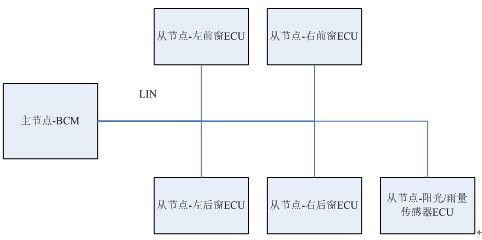
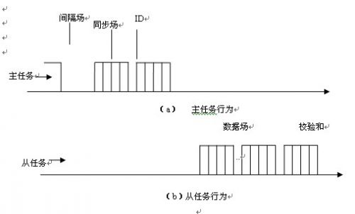
introduction: This article refers to the address: http:// With the improvement of automobile intelligence and the need for upgrading, automotive electronic systems are developing from centralized control to distributed control based on bus. In the field of body control, it is effective as a control area network (CAN) bus. In addition, the local interconnect network (LIN) bus solves the problem of cost increase caused by distributed control with its low cost, and is large in the domestic car body electronic system with low communication rate requirement and higher cost requirement. Scale application. The author designed a body controller (BCM, Body Control Module) for the body control system of a domestic car based on LIN bus. As the main node of the LIN bus network, BCM realizes multi-channel switching, pulse quantity detection and load. At the same time of control and other functions, it manages and manages the communication of the entire LIN network, realizes the interaction with the command and state of the LIN slave node, and realizes the network management function. The LIN network architecture is shown in Figure 1: Figure 1 Body LIN network architecture Combining the BCM design experience, the author first analyzes the architecture and communication mechanism of the LIN protocol, and then introduces the design technology of the master node from the implementation of the data link layer, application layer and network management. 1 Protocol analysis: The LIN bus adopts a master-slave network architecture [1]. The master node controls the network signal flow in a time slice rotation manner, determines which frame to transmit and maintains the correct timing between frames, and receives the frame header from the node and according to its identifier. The ID (Identifier) ​​determines how to respond. LIN communication is based on the behavioral model of the primary task and the secondary task. As shown in Figure 2, the primary task is responsible for generating and transmitting the correct message header, and the task is responsible for responding to the message header. This approach eliminates the need for bus arbitration and guarantees signal transmission delay times in the worst case, with network load controllable and avoiding bus collisions. Figure 2 LIN communication behavior model In the LIN bus system, the implementation of the master node is the most complicated. The following describes the design and implementation of the LIN protocol of the master node from three aspects: data link layer, application layer and network management. 2 LIN protocol design 2.1 Data Link Layer: The LIN bus is based on an asynchronous serial communication interface. The SCI serial data link format of the 8N1 format is used in the underlying transmission [2]: 8 data bits + 1 stop bit, no parity, and because the LIN bus is at the physical layer. The upper one is a single line, and the receiving interrupt is also triggered when transmitting, so that the LIN data link layer can be uniformly implemented in the serial communication interface (SCI, serial comuunication interface) receiving interrupt processing function. Figure 2 shows the LIN message format: LIN message consists of two parts: the frame header and the response [3]. The frame header includes the interval field, the sync field and the ID. The response includes the data field and the checksum. According to the LIN message format, the state machine is designed to define the state of each component of the message. With the state transition of the LIN message transmission and reception process, the LIN data link layer can be realized in the form of a state machine. I will not go into details here. I can refer to the author's article "Application of finite state machine in LIN bus development" [4]. 2.2 Application layer: The application layer protocol mainly defines the message schedule and the message signal matrix. The master node needs to implement the LIN message transmission scheduling and the LIN signal extraction and filling according to the schedule. The schedule is a circular sequence of messages, each of which contains a message and the length of the time slice it occupies. The master node implements timing and rotation of the time slice according to the schedule. When a packet time slice arrives, the BCM sends a frame header including a spacer field, a synchronization field, and a protected indentifier (PID) [5]. The response mode (send or receive data field and checksum) is then determined by each node based on the PID. When the time slice is full, the schedule entry is switched, and the next message is transmitted, so that the transmission scheduling of the LIN message is realized. The schedule entry structure is designed as follows: Typedef struct { Uchar handle;/*the schedule table index*/ Uchar pid; l_Resp_mode mode;/*means BCM receive the datafield or send the datafiled */ Uchar datalen; Uchar *data; Uchar ticks;/*the time slot length*/ }l_sch_table_item; The LIN message schedule is an array of l_sch_table_item structures. The handle indexes the specific schedule entries, which are accumulated with the switching of the time slice. When the switch is added to the end of the schedule table, the handle is set to the index of the schedule header, and then rotated again. ; pid is the Protected ID of the LIN message, indicating which message is transmitted in the time slot; mode indicates whether the response of the message is sent by the BCM or sent by other nodes; data is the address of the data field, pointing to the message corresponding to the entry. Data field, datalen is the length of the data field; ticks defines the length of the time slot, which determines the time of the time slice. When the time is full, it switches to the next time slot for the next message transmission. The LIN signal matrix defines the meaning, length and position of the signal contained in the data field of each message. The author implements the filling and extraction of the LIN signal in a subtle way. Firstly, according to the definition of the signal matrix, a structure is designed separately for each message data field. The structure member variables respectively correspond to the signals in the message, and then when the schedule is initialized, each message structure variable is The address is assigned to *data in the schedule entry (see the l_sch_table_item structure definition above), so that for the message sent by the BCM to the data field, the LIN signal is realized by directly assigning the value of the member variable in the message structure variable. The padding, when scheduling the transmission of the message, the data of the transmitted data field is the value that has been filled and updated. For the message received by the BCM, when the time slot is rotated, the *data in the schedule entry already contains the data field of the message, which can be directly extracted and used [6]. 2.3 Network Management The LIN protocol defines the network management function to achieve sleep and wake-up of the LIN network. The BCM acts as the master node of the body LIN network and controls the sleep of all LIN nodes. There are two ways to enter hibernation: 1. The BCM suspends the rotation of the main schedule, and maintains no data on the bus. After 4S, the slave automatically enters sleep; 2. The BCM broadcasts a diagnostic request frame, that is, a sleep frame, with the first byte of the data field being 0 on the bus, and the slave node enters sleep after receiving the frame. Wake-up is achieved by sending a wake-up signal on the bus. The wake-up signal is a dominant bit that lasts longer than 150us. Each node in the LIN network has a wake-up function. When the BCM wakes up other nodes, it can send data 0. Because the maximum rate of the LIN bus is 20K, the data 0 will pull the LIN bus down to a dominant bit of at least 450us. When the BCM is woken up by other nodes, it is necessary to disable the SCI function of the SCI module when it enters sleep, enable its IO function and enable interrupt wake-up, so that when a dominant bit appears on the bus, it can be woken up, detecting the IO pin. The low level duration determines whether it is a valid wake-up signal. If yes, the schedule is switched to the main schedule to start normal communication. If it is an invalid wake-up signal, it is considered as a glitch and immediately goes to sleep again. Conclusion The author combines the experience of designing a body controller based on LIN bus, deeply analyzes the LIN protocol specification and its communication principle, introduces the data link layer protocol specification and its implementation technology in detail, defines the main tasks of the application layer and gives the design. The method analyzes the mechanism of LIN network management and gives a concrete implementation. It has a good reference for engineers engaged in LIN development.
Laser Radar contains LSPD Safety Laser Scanner and LS laser radar. LSPD safety laser scanner is type 3 with CE certificate. It can be used for agv safety and industrial area protection. LS laser radar is for agv guide. Many famous agv manufacturers has installed LS laser radar to guide their agvs. Our cooperating brand contains Quicktron, Mushiny, Aresbots, etc. Feedback from customers are quite posotive.
Laser Radar Laser Radar,Auto Guided Vehicle Guide Radar,Sick Laser Radar,Safety Scanner,Safety Laser Scanner,Ls Series Laser Radar Jining KeLi Photoelectronic Industrial Co.,Ltd , https://www.sdkelien.com