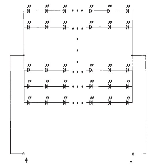
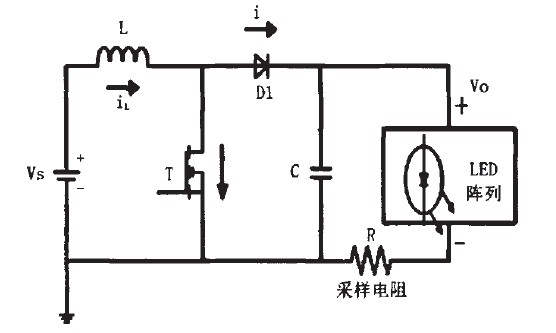
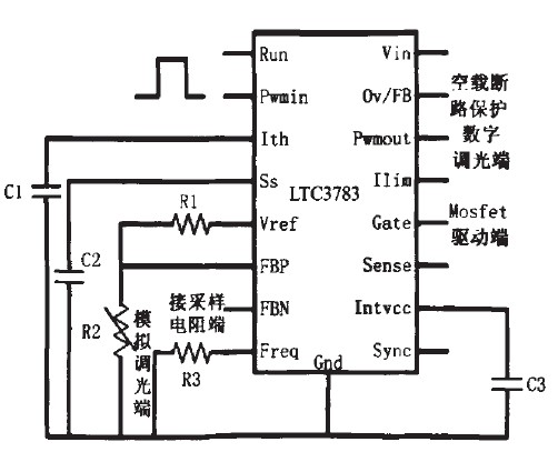
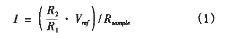
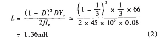
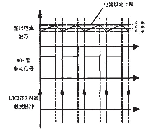
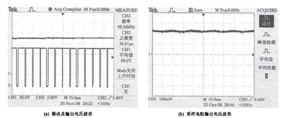
Abstract: This paper introduces a circuit design based on battery-powered LED lighting system. With Boost as the power circuit topology, the reliability of the illumination is improved by properly arranging the LED array. This circuit is designed to simulate dimming and digital dimming of LEDs at the same time, and the system is suitable for LED arrays with power ranging from a few watts to tens of watts, and batteries with terminal voltages ranging from 6-36V, thus enabling maintenance of the product - - When the LED needs to be replaced or the battery needs to be replaced, as long as the above requirements are met, the system can operate normally and stably without replacing the circuit module. Foreword Due to its high luminous efficiency, high reliability, long life and other advantages, light-emitting diodes (LEDs) are widely used in lighting, signal display, imaging, etc., and are widely regarded as a traditional light source that replaces incandescent lamps and fluorescent lamps. New light source. There are many ways to drive an LED, and the easiest way is to connect the LED in series with the current limiting resistor and then supply it from a voltage source. The advantage of this type of drive is that the circuit is simple, but there are also many drawbacks. The first is low efficiency, the step-down resistor consumes a lot of power, and may even exceed the power consumed by the LED. Secondly, the stable voltage capability is extremely poor, and the VI curve of the LED has a negative temperature characteristic. As the junction temperature increases, the flow The current through the LED will be larger and larger. Therefore, if the drive current is not controlled, the LED is easily burned, and even if it is not burned, the life will be greatly shortened. Therefore, current control is required when driving high power LEDs. In addition, the illuminance of the LED light source is directly related to the current, so the illumination current of the LED is controlled and the illuminance is also controlled. 1 system design The principle block diagram of the system is shown in Figure 1. The power supply is a lead-acid battery, and the load is an array of LEDs. The LTC3783 is used as a controller to implement PWM control. This circuit is designed to simulate dimming and digital dimming of LEDs simultaneously. And the system can work normally for LED arrays with power from several watts to tens of watts and batteries with terminal voltage range from 6-36v, so that when the product is to be repaired - need to replace the LED or need to replace the battery, as long as it meets The above requirements, the system can work normally and stably without replacing the circuit module. Figure 1 System block diagram Due to various limitations such as heat generation and heat dissipation technology, the power of a single LED cannot be made as large as a conventional light source. A LED with a power of 1w is a high-power LED. In practical applications, an array of multiple low-power LEDs is usually used to meet higher illumination requirements and achieve low cost, as shown in FIG. 2 . Figure 2 LED array diagram There are another significant advantages to using LED arrays. We know that LEDs may be shorted and broken due to certain faults. When a string, the LED in the branch branch is short-circuited, the other LEDs in the branch can still work normally. Although the current through the LED may rise, due to the large number of LEDs, the rising current is not large, and the rising current does not exceed the allowable operating range of the LED. When an LED in a series branch is broken, the string of LEDs is extinguished. However, since the array is composed of a plurality of LED strings, other LED strings can still work, and share the current in the extinguished LED string, but since the LED has more branches, the rising current is not large, and the rising current does not exceed The working range allowed by the LED. Therefore, it is obvious that the LED array has relatively higher stability and reliability. 1. Moreover, for a certain number of LED arrays, when the number of branches is matched with the number of LEDs in the branch, it will be more advantageous to enhance the LED. Reliability and stability of component operation. In the experiment, an array of 8 strings of 20 LEDs per string and an array of 12 strings and 12 LEDs per string were fabricated. The LED used is an O.1w bullet-shaped LED with a rated forward voltage drop range of 3.0-3.3V and a rated forward current range of 10-30 mA. The LED design is operated at 20 mA in the experiment, which can reduce the heat dissipation. And there is enough current margin when the LED has a short circuit fault. 1.2 B00st converter and controller improvement The schematic diagram of the main circuit is shown in Figure 3. For the main circuit, the current of the constant current control converts the current into a voltage through the sampling resistor R, and the controller can realize the voltage on the constant sampling resistor by turning on and off the switching tube, thereby realizing the current of the constant LED array. If the voltage value on the controller's constant sampling resistor can be adjusted, analog dimming of the LED will be achieved. Based on the above ideas, the application improvement of LTC3783 is shown in Figure 4. Figure 3 main circuit schematic Figure 4 Schematic diagram of the control circuit In Figure 4, the sampling resistor is terminated to the FBN negative feedback terminal of the controller instead of the sampling sense terminal. The reference level Vref is divided into the positive feedback end of the FBP by means of voltage division, and the fixed value resistor is replaced by the adjustable resistor R2. To achieve a voltage target value on a constant sampling resistor, simply adjust the adjustable resistor. The constant LED current value is determined by the voltage value across the constant sampling resistor. which is: Through the above application innovation of the controller LTC3783, the analog dimming of the LED is realized, and at the same time, when the LED array needs to be replaced, as long as the power is not too large, there is no need to redesign the circuit. Combined with the characteristics of the controller itself, this circuit design can also digitally dim LEDs, for LED arrays with power ranging from a few watts to tens of watts and batteries with terminal voltages ranging from 6-36V. The design of the converter should meet the following requirements: (1) When using an array of 8 strings and 20 LEDs per string as the load: Output voltage Vo: 60~66V Output current Io: 0.16A (constant current value) Working frequency f: 45kHz When powered by a 12V battery: Voltage ratio M: 5-5.5 Duty cycle D: 0.800-0.818 When powered by a 24V battery: Voltage ratio M: 2.5~2.75 Duty cycle D: O.600-O.636 (2) When using a 12-string array of 12 LEDs per string as the load: Output voltage Vo: 36-39.6V Output current Io: 0.24A (constant current value) Working frequency f: 45kHz When powered by a 12v battery: Voltage ratio M: 3-3.3 Duty cycle D: 0.667-0.697 When powered by a 24v battery: Voltage ratio M: 1.5~1.65 Duty cycle D: 0.333~0.394 During commissioning, a constant current target value can be achieved by simply adjusting the adjustable resistor R2, and the duty cycle is adjusted by the controller. The size of the capacitor in the Boost circuit determines the magnitude of the load voltage ripple. The specific capacitor value can be selected according to the design needs. The inductance value in the circuit determines the current ripple. In order to facilitate the design of the system parameters, the design system usually works in the current continuous mode. This system considers that in extreme cases, the dimming to 10mA inductor current is still continuous, the values ​​are as follows: Considering a certain margin, the final selection of the inductance is 1.5mH. If the inductance is too small, it is easy to cause the output power of the design circuit to be insufficient when the load power is large, so that the load cannot work normally. 1.3 constant current control In fact, the output current of the converter is not completely constant, but has a certain ripple, as shown in Figure 5. When the MOS transistor is turned on, the output current rises, and when it is turned off, it drops. The control strategy here is to turn off the MOS transistor when the output current reaches the set upper limit, so that the current drops until the trigger pulse (45 kHz frequency) inside the next LTC3783 controller comes into a drive signal to turn it on again. The specific set current can be achieved by adjusting the adjustable resistor. Since the output current is directly sampled to form a feedback, no matter what changes in the VI characteristics of the LED, the feedback can be adjusted to maintain the output current. Figure 5 Schematic diagram of the control strategy 2 experimental results The upper waveform in Fig. 6(a) is the output voltage, the lower waveform is the switching tube driving waveform, and Fig. 6(b) is the corresponding sampling resistor output voltage waveform. The spikes in this waveform are parasitic inductance and capacitance. The noise caused. The two sets of waveforms in Figure 6 are powered by a 12V battery, with an experimental waveform of an array of 8 strings and 20 LEDs per string. Figure 6 converter output waveform From the data measured in Figure 6(a), the duty cycle can be calculated as: It is consistent with the theoretical value calculated above: duty ratio D: O.800~0.818. After experiment, under the power supply of 12V battery, with a 12-string, 12-string LED array as the load, and a terminal voltage of 24V battery to supply power to the above two LED arrays, the duty ratio is the same as the previous theoretical analysis value. Consistent and able to work steadily. Therefore, it is proved that the system can work normally for the battery array with a terminal voltage range from 6-36V for the LED array in the high power range. Moreover, in the maintenance of the product - when it is necessary to replace the LED or need to replace the battery, as long as the above requirements are met, the system can work normally and stably without replacing the circuit module. 3 conclusions Boost circuit not only can boost, but also requires less components in the topology itself, which is beneficial to improve efficiency, and is very suitable for applications that need to supply batteries to LEDs. Analog dimming and digital dimming of LEDs were achieved through the application of innovations to the controller LTC3783. And the designed system can work normally for LED arrays with power from several watts to tens of watts, batteries with terminal voltage range from 6-36V, and maintenance of the product - need to replace the LED or when the battery needs to be replaced, As long as the above requirements are met, the system can operate normally and stably without replacing the circuit module. [1]. LTC3783 datasheet http://
Glass tube fuses are made by glass shell, some metal wires and two brass caps. Fuse is small safety part in an electrical device or piece of machinery that causes it to stop working if the electric current is too high, and so prevents fires or other dangers. Fuse in the abnormal current increases to a certain height and heat, its own fuse to cut off the current, to protect the safe operation of the circuit fuse protection power equipment with current overheating damage, avoid electronic equipment serious damage caused by internal fault. When a circuit breaks down or is abnormal, the current increases with the current and the increased current may damage some important components in the circuit, and it may also burn the circuit and even cause a fire. If correctly placed in the circuit fuse, the fuse will be abnormal current increases to a certain height and heat, its own fuse to cut off the current, so as to protect the safe operation of the circuit.
Auto Glass Tube Fuses Auto Glass Tube Fuses,Max Fuse,High Quality Blade Fuse,Fuse Block Heshan Jianhao Lighting Industrial Co., Ltd. , https://www.sunclubtw.com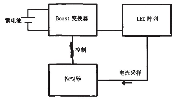
references:
[2]. FBP datasheet http://
Battery-powered adaptive LED lighting system
3 times
Window._bd_share_config = { "common": { "bdSnsKey": {}, "bdText": "", "bdMini": "2", "bdMiniList": false, "bdPic": "", "bdStyle": " 0", "bdSize": "24" }, "share": {}, "image": { "viewList": ["qzone", "tsina", "tqq", "renren", "weixin"], "viewText": "Share to:", "viewSize": "16" }, "selectShare": { "bdContainerClass": null, "bdSelectMiniList": ["qzone", "tsina", "tqq", "renren" , "weixin"] } }; with (document) 0[(getElementsByTagName('head')[0] || body).appendChild(createElement('script')).src = 'http://bdimg.share. Baidu.com/static/api/js/share.js?v=89860593.js?cdnversion=' + ~(-new Date() / 36e5)];