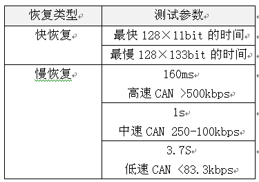
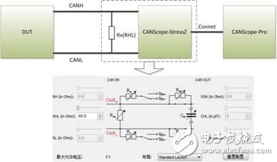
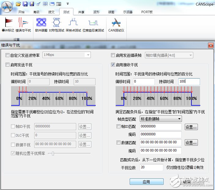
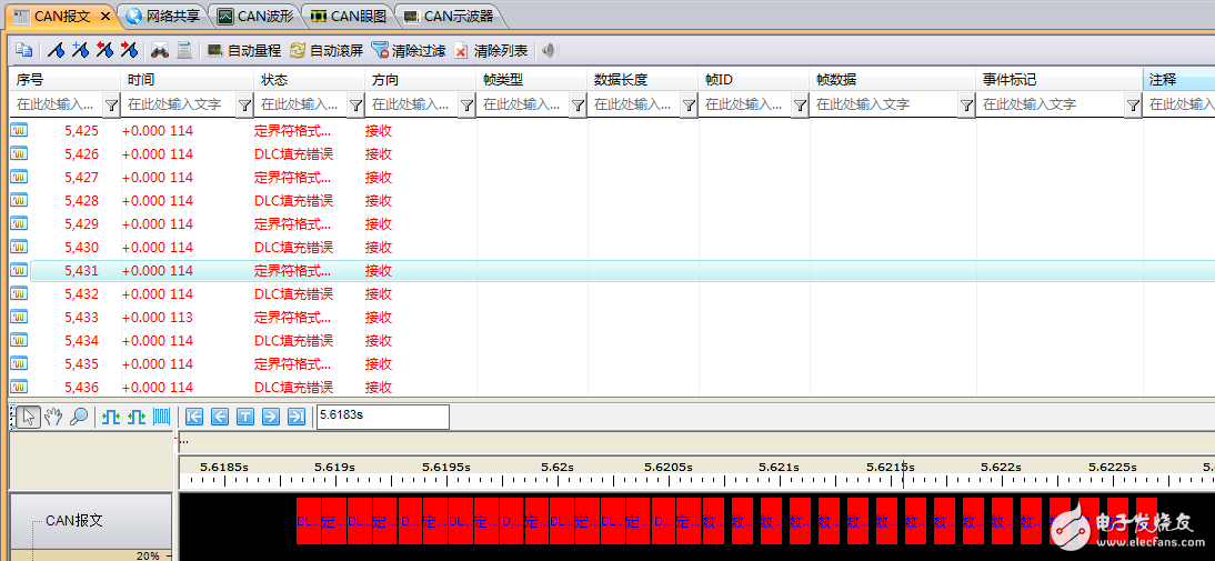
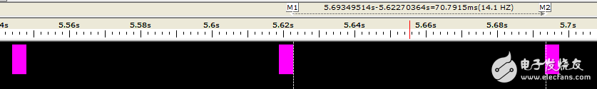
When the CAN communication fails, the CAN controller will cause the faulty node to enter the passive error state from the active error state, and even enter the bus off state, so that the faulty node is disconnected from the bus communication, so that it does not affect the communication of the normal node, but The control scheme will cause the node that enters the bus off state to continue to be unable to interact with other nodes before the system is powered back on. If the node is only temporarily faulty, then the node can achieve self-recovery function, which is more superior. Control method. Therefore, the CAN bus design specification strictly regulates the Busoff self-recovery mode of the CAN node, and fully considers the handling of sporadic and continuous faults. The specific specifications are shown in Table 1, which is the test standard "Recovery time after GMW14242 BusOff". At present, many OEMs have put forward corresponding control requirements for the recovery time of Busoff for their system supplier equipment. Table 1 Recovery time standard after BusOff Therefore, each manufacturer must perform the recovery time test after the Busout of the CAN node DUT (device under test) before the product is put into use. However, since the test is to interfere with the communication signal and judge whether the node has entered the Busoff state, and then it can measure the recovery time, even if the oscilloscope is used to observe the signal, it is difficult to make an accurate measurement. In order to solve this problem, Guangzhou Zhiyuan Electronics Co., Ltd. improved the test method, using CANScope-Pro bus analyzer, CANScope-StressZ expansion board for fully automatic test operation, after completing the operation, using its transient flow analysis plug-in, Prepare to judge the self-recovery time of the CAN node after Busoff. Test principle: The DUT sends a message by the test device, and then creates interference (CANH to ground short, destroy frame content, etc.), causing the DUT packet to fail to transmit. After causing 32 consecutive transmission failures, the DUT enters the BusOff state. The time interval between the measurement of the next DUT transmission message is the recovery time after BusOff. The test plan is as follows: 1. This test uses CANScope-Pro and CANScope-StressZ. After the DUT is powered on, after initializing the controller, it sends a CAN message or triggers the DUT to send a message through CANScope. CANScope checks the bus response. As shown in Figure 1, a test connection is made. The RHL that enables the CANScope-StressZ is 60 ohms. Figure 1 Processing test connection after BusOff 2. Start CANScope-Pro, adjust RHL to 60 ohms, set the same baud rate as the DUT under test, and click Open. The control DUT can issue a variety of expected messages and can be received by CANScope-Pro. 3. Open CANScope-Pro's “Errors and Interferencesâ€, enable “Accept Interferenceâ€, and change the “Duration†to 100 and click “Applyâ€. as shown in picture 2. At this point, a higher interference strength can be achieved, and the messages sent by each DUT can be interfered. Figure 2 Enable Receive Interference 4. After a period of interference, click “Stop†on the message interface. Open CANScope-Pro's “Flow Analysis†and find a continuous 32 interference results, as shown in Figure 3. Figure 3 Traffic Analysis Interference Results Then reduce the traffic analysis interface and measure the time interval between the two interference groups, which is the recovery time after BusOff. As shown in Figure 4, it is 70.7915ms. Figure 4 Recovery time after BusOff CANScope analyzer is a comprehensive CAN bus development and testing tool developed by Zhou Ligong Zhiyuan Electronics. It integrates mass storage oscilloscope, network analyzer, bit error rate analyzer, protocol analyzer and reliability test tool. Integrate and correlate various instruments organically; redefine the development and test methods of CAN bus, and evaluate the correctness, reliability and rationality of CAN network communication in multiple angles; help users quickly locate faulty nodes and solve CAN bus Various issues of application.
FGI`s FGSVG series low voltage dynamic reactive power compensation and harmonic devices are mainly composed of control panels, energy storage capacitors, reactors, IGBT, inverters, fuses and other devices. The Low Voltage Static Synchronous Compensator (STATCOM) has functions such as compensating reactive power, controlling harmonics, balancing negative sequence current and suppressing voltage flicker.
Low Voltage Static Synchronous Compensator Svc Static Var Compensator,Low Voltage Synchronous Compensator,Low Voltage Static Compensator,Low Voltage Static Synchronous Compensator,Statcom Manufacturers,Power Quality Products FGI SCIENCE AND TECHNOLOGY CO., LTD , https://www.fgi-tech.com