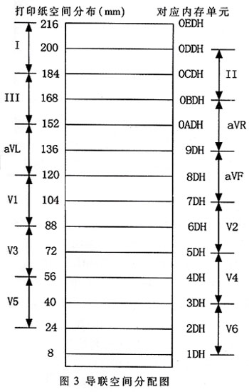
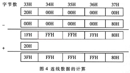
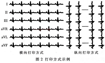
At present, most of the electrocardiographs commonly used in hospitals in China are electromechanical, that is, the electrocardiogram is detected by the electrodes, and the direct recording is performed after amplification. There are disadvantages such as low printing efficiency, serious noise pollution, and distortion of the electrocardiogram waveform. In contrast, digital electrocardiographs implement noise suppression and ECG parameters extraction through software, and use digital printers to output ECG graphics, which can provide medical staff with more perfect ECG and more diagnostic information, which will become the market development. Trends have broader application prospects. Since the data collected by the digital ECG machine through the ADC is discrete, it should be restored to the original ECG graphic on the drawing, in addition to the data and the discrete points on the drawing, but also according to the trend of signal changes, at these points Connect between lines to make it a continuous figure. Synchronizing, accurately and quickly printing ECG data, especially multi-lead ECG data, is the difficulty and key to the development of the whole system. The efficient printing algorithm is of great significance for the development of digital electrocardiograph. This article refers to the address: http:// With the development of electronic technology, printers have been widely used in various fields, becoming an important data output means for various intelligent digital instrumentation. Among them, thermal printers are more and more popular because of their small size, light weight, high reliability, clear printing characters, no noise, and uniform paper feeding. They are the first to become small medical instruments such as electrocardiographs. The following is a 12-lead synchronous electrocardiograph developed by the author's research group. This paper introduces the application of serial thermal printer with ordinary 52 single-chip microcomputer as the main control chip to realize ECG graphic printing in various ways, and focuses on the 12-lead synchronous printing method. Program implementation. 1 system hardware design The system is equipped with a built-in digital printer, which is mainly composed of a thermal print head (W216-QS) and a stepper motor. The W126-QS dot matrix thermal print head prints data using a serial input. It contains not only a 1728 shift bit register made up of C-MOS integrated chips, but also a heating element made by a high-density thick film process. These heating elements are driven by latching and switching transistors to produce 1728 dots on thermal paper with a corresponding print width of 216 mm and a resolution of 8 dots/mm. The print data required for the thermal printhead is serial data, and the data transfer follows the communication protocol of the SPI port. The system uses the working mode of the mouth line analog SPI to communicate with the print head. The circuit is shown in Figure 1. Considering that the internal processing of the 52 MCU has 256 bytes of internal RAM, the system also expands one piece of HM628128 to store 12-lead ECG data and intermediate conversion results. 2 system software preparation Two key issues in digital printing: 1 how to convert ECG data into print data; 2 if the data is output to a digital printer. The usual method is to convert the data and output it to the printer for printing. This saves memory space; the disadvantage is that the program is complicated to implement, the versatility is poor (the data output program is different for different printing methods), the system function is not easy to expand, the data conversion and output must take into account the print point position, and each output of the data must be called. A program that increases system overhead. This method is not used in the system software, but a 216-byte print buffer is opened in the memory, and 1728 points of the thermal print head are corresponding to 216×8-bit data, and the line data to be printed is converted every time. Then output. In this way, only the print position and mode are considered in the data conversion. The output program only needs to output 216 bytes of data bit by bit, and only needs to call the output subroutine once for printing one line of data, and the system overhead is byte. The disadvantage is that it takes up system resources, which is especially evident in the 12-lead simultaneous printing. The system program realizes three printing modes: printing 12 lead data twice, printing 6 guides, 12 guides synchronous printing, and vertical printing (printing effect as shown in Fig. 2). The analog SPI port is implemented in each print program to send print data to the subroutine of the digital printer. The difference is how to convert the ECG data into print data. 2.1 I / O line line analog SPI port SPI (Serial Peripheral InteRFace) bus serial port is a synchronous serial peripheral interface proposed by Motorola, which communicates through four wires: clock line (SPKCLK), data output line (SPIMISO), data output line (SPIMOSI), The chip select line (CS) internally performs string-and-parallel-serial conversion through the SPIDAT register. It mainly works in a master-slave system. A master device can have multiple slave devices. The master device controls the bus collision through the chip select line, so that only one slave device can exchange data with the slave device at the same time. The system application serial thermal array printer data transmission uses SPI timing, but the ordinary 52 single-chip microcomputer has no SPI port, so the I/O line line is used to simulate the SPI timing. Considering that the MCU in the system always transmits data as the master device, and the digital printer always receives data as the only slave device, it only needs to simulate the SPI port clock line (SPIKCLK) and data output line (SPIMOSI) with the port line. Simulate SPIDAT to complete the parallel-to-serial conversion. As mentioned before, the print head prints 1728 points and the resolution is 8mm/mV, corresponding to 216 bytes of data. For this purpose, 216 bytes of space are allocated from the internal RAM as a print buffer, and the program is buffered. The area reads data sequentially, and the serial data converted into parallel data is sequentially sent to the shift register of the printer under the control of the analog clock line. After the end, the LATCH latch signal and the print head heating pulse STROBE are sent, thereby being hot. The sensitive printing paper prints a line of ECG graphics, and the stepping motor can drive the paper to print continuously. The SPI port simulation program is as follows: OUTPUT: Field protection LCALL INTRAM ; Initialize internal print buffer MOV R0, #Dat_Buff ; Initialize R0 as the last bit address of the buffer MOV A, @R0 ; read data from buffer MOV R7, #08H ; Initialize R7 control and / string data conversion CONT_CHG: RRC A; implements parallel-to-serial conversion on the right shift of the ACC loop MOV P1.3, C sends serial data to the printer SETB P1.1; analog SPI clock NOP CLR P1.1 DJNZ R7, CONT_CHG; judge whether 1 byte of data is converted DEC R0 ; addressing the next byte CJNE R0, #15H, DAT_OUT; judge whether the data is completely converted CLR P1.2; generate data latch signal NOP SETB P1.2 NOP CLR P1.0; generating heat pulse LCALL HEATDLY ; call heating delay program SETB P1.1 LCALL MOTOR_RUN ; stepper motor paper Recovery site RET 2.2 Printing algorithm The digital printer essentially realizes the correspondence between the data and the printing point, that is to say, the 8-bit ECG data range is from 0 to 255, corresponding to 256 points on the thermal printing paper, and the point on the paper is changed by the heating sensitive unit. Black shows the size of the data. Therefore, it is necessary to convert data representing the actual electrocardiographic magnitude (hereinafter referred to as raw data) into data capable of indicating the position of the heating point (hereinafter referred to as position data), and sequentially print out the points corresponding to the electrocardiographic data by the control of the position data. , you can get an electrocardiogram. However, since the ECG data obtained by the system analog-to-digital converter is discrete, if only the corresponding points are printed out, only a few discrete points are obtained. To obtain a continuous ECG pattern, the adjacent discrete points need to be determined according to certain The algorithm links them up, and the discrete point routing algorithm is different for both vertical and horizontal printing. Due to space limitations, in the implementation of the printing method described below, only the horizontal 12-lead synchronous printing and the vertical printing are described in detail, and the 6-lead printing only introduces its implementation idea. 2.2.1 Horizontal 6-lead printing The length of the ECG paper is 216mm, and 32mm is allocated for each lead ECG signal, corresponding to 32 consecutive bytes in the print buffer. The position data after the print data conversion is stored in these 32 bytes. The 12-lead ECG data is divided into two groups, and the remaining 6-lead data is printed when a group is printed. The specific implementation process can refer to the horizontal 12-lead printing mode. 2.2.2 Horizontal 12-lead synchronous printing In the process of implementing the 6-lead printing method, it is noted that in most cases, only the main peak of the QRS wave in a finished ECG waveform can be filled with the entire space, and the other bands have smaller amplitudes and occupy less space. More information can be provided, and the 12-lead print is printed separately, which is not conducive to doctors comparing the ECG waveforms of different leads at the same time. With 12-lead synchronous printing, although there will be partial overlap of waveforms, it has little effect in the diagnosis of some heart diseases, and can obtain more intuitive effects. The basic idea of ​​the 12-lead synchronous printing program is the same as that of the 6-lead synchronous printing. The difference is that the 12-lead data is printed on the 216 mm wide printing paper at the same time, and the phenomenon that the different lead electrocardiograms overlap is inevitable. The corresponding memory unit will also be reused. If the 6-lead printing program is simply applied, the data of the previous lead will be flushed by the adjacent lead data, so that the graphic cannot be displayed correctly. Figure 3 shows the thermal paper space and buffer memory unit allocated for each lead (here assuming the cache address is 0x1DH ~ 0xEDH). It can be seen from Fig. 3 that except for the first 16 mm space of the I lead and the rear 16 mm space of the V6 lead are not multiplexed, the other space of the printing paper is shared by the two leads. The internal RAM usage is similar. To this end, an external print buffer image area is opened in the external RAM (the size is 216 bytes, the lower 8 bits of the unit address are the same as the corresponding unit of the memory, such as the internal RAM 0x1DH unit corresponding to the external RAM 0xXX1DH), and the 12-lead Divided into two groups: one group (I, III, aVL, V1, V3, V5) is still stored in the internal memory, while the other group (II, aVF, V2, V4, V6) is stored in the external image area, at 12 leads When the first line data is converted to be printed, the two parts can be matched according to the corresponding unit. This will not only solve the above problems, but also save internal resources and reduce the difficulty of programming. As mentioned above, the printing space occupied by different leads is different. Therefore, for a certain lead ECG signal, the printing interval is first determined, and then the relative position of the printing data in the interval is determined. Assume that the starting byte of the print space occupied by a certain lead is the nth byte, and the electrocardiogram data to be printed is m, m is divided by 8, the quotient is k, and the remainder is 1, then the ECG data corresponds to The first bit of the logarithmic (nk) byte. That is, the position data corresponding to the electrocardiographic data is the (nk)th byte (the 1st position of the byte is 1, and the other bits are cleared). Therefore, when printing this ECG data, only the first bit of the (nk)th byte of the 32-byte print data to be transmitted by the lead is 1, and all others are 0. Similar to the liquid crystal display, for ECG signals of one lead, to achieve ECG printing, two ECG data must be connected to the line. That is, for an ECG curve, the initial display data point shows only 1 point in the start column; from the second data point, the line segment between the previous data point and the current data point is displayed in the next column. On thermal paper, it is shown that the points between the two data points are heated, and corresponding to the memory, the data between the two points is set to 1. For the ECG signal of the lead, the first ECG data is read first and converted into 32-bit position data for direct printing. Starting from the second ECG data, in addition to being converted into position data, it is compared with the previous data, and the position data corresponding to the large number is subtracted from the decimal number, and then the result is added to the position data of the large number. The result is 32 bytes of data that should be sent for this ECG data, that is, the operation of connecting with the previous ECG data is completed. The analysis found that the connection algorithm only affects the data between non-zero bytes in the two adjacent locations. To simplify the calculation, only these bytes need to be subtracted without having to calculate all 32 bytes. For addition, it is only necessary to add non-zero bytes in the corresponding position data of the large number, that is, perform single-byte addition. For example, for the lead V6 ECG signal, the previous data 37H, the next data is 55H, and the print interval allocated by the lead V6 is 1DH to 3DH. According to the position data conversion algorithm, the position data of 37H is the 37th HQ. The content of this byte is 80H, the other bytes are all 00H; the location data of 55H is the 33H byte, the content of this byte is 20H, and the other bytes are 00H. Since 37H<55H, it should be the position data of the ECG data 55H minus the position data of 33H, and the calculation is as shown in Fig. 4. 2.3 Vertical print program Longitudinal printing enables simultaneous display of 12-lead data without overlap. In this way, the doctor can refer to the comparison of the trends of the waveforms at the same time to facilitate the diagnosis of the disease. The thermal paper has a width of 216mm and a resolution of 8dot/mm, so that it can print up to 1728 points, and these points correspond to 1728 consecutive ECG data of a certain lead, that is, the nth data of the lead sequence. Corresponds to the nth point in the line graph. Longitudinal printing still solves the problem of connecting discrete points compared to die-printing; however, compared to horizontal sequential printing, which means printing dots in chronological printing, the difficulty lies in the need to have multiple values ​​of the same magnitude at different times. The dots are printed at the same time, that is, the print dots are printed in spatial order. First define a memory unit to store the scan value, so that it changes from the current channel data maximum value to 0, and compares it with each data of the channel in turn: the same point is traced; the small is not traced; the larger the current heart The two points adjacent to the electrical data are compared with the scan values. As long as one of them is larger than the scan value, the corresponding point is traced, and the data to be traced is set to 1 corresponding to the memory. For example, if the first byte of the print memory buffer is n, the size is 216 bytes, and the mth ECG data of a current lead sequence is v, and the scan value at this time is w: 1v>w, Then continue to compare the m+1th data; 2v=w, then the corresponding point needs to be traced; 3v
Sony is a great brand for the laptops, and there
are very few laptop manufacturers that compete with Sony when it comes to the
style and aesthetics of their laptop designs. As a result, Sony has one of the
most loyal customer bases within the laptop and Laptop Charger.
For sony laptop
charger, the best seller is sony vaio lapotp charger. Yidashun can offer a
full brand OEM replacement laptop Adapter for sony. The common Sony laptop charger specification has 60W 64W 16V, 39W 76W 80W 100W 120W 150W 19.5V etc, and the dc
tip has common 4.8*1.7mm and 6.5*4.4mm with pin inside.
All our sony vaio adapter is Brand New Replacement Product, works as Genuine parts, 100% OEM Compatible!!
and Our laptop adapter with smart IC can protect your laptop with over current protection, over load
protection, short circuit protection and over heat protection.
Sony Laptop Charger,Sony Vaio Charger,Sony Vaio Laptop Charger,Sony Laptop Adapter Shenzhen Yidashun Technology Co., Ltd. , https://www.ydsadapter.com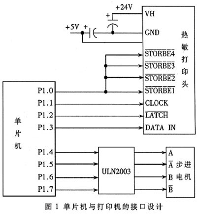
DAT_OUT: