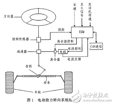
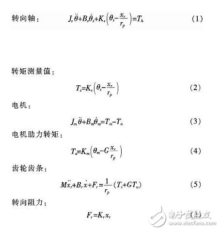
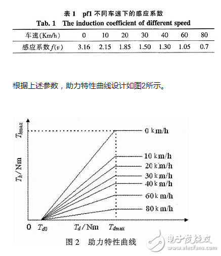
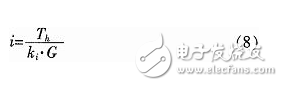
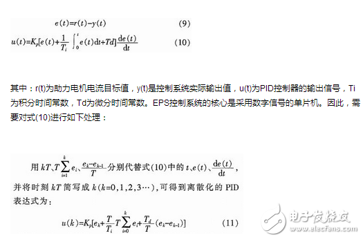
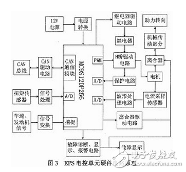
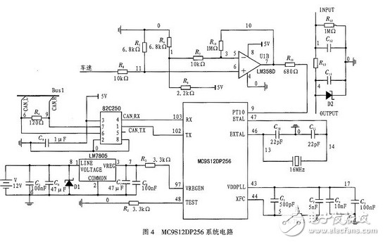
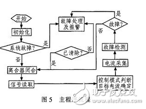
The steering system is an important part of the car, and its performance directly affects the stability and safety of the car. The early car steering system was a purely mechanical steering system with no power. The steering power was completely provided by the driver and the driving experience was poor. Since the 1930s, power steering systems have emerged. At present, there are three main forms of automotive power steering: Hydraulic Power Steering (HPS), Electric Hydraulic Power Steeing (EHPS), and Electric Power Steering System (EPS). ). Compared with the first two, EPS provides auxiliary torque from the motor, without oil system, which greatly reduces the complexity of the steering system of the car, and has obvious advantages in fuel efficiency, modularity, power-assisting effect and environmental friendliness. . According to the position of the EPS assist motor on the gear and the steering column assembly, the EPS system is divided into four types: steering column assist type, rack assist type, pinion assist type and double pinion assist type. Pinion and steering column assist are used in light vehicles, and double pinion assist is used in heavy vehicles. They are composed of three basic components: an electric control unit (ECU), a booster motor and a torque sensor mounted on the steering column. For the small car, the EPS controller is designed with the 16-bit single chip MC9S12DP256 of Freescale Company as the core. The structure of the electric power steering system is shown in Figure 1. It is mainly composed of a steering wheel, a torque sensor, an electronic control unit (ECU), a motor, an electromagnetic clutch, a speed reduction mechanism, and a rack and pinion steering gear. After the engine is ignited, the steering torque is measured by a torque sensor mounted on the steering shaft and sent to the ECU. The ECU calculates a boost characteristic curve and a control strategy based on the torque and the vehicle speed. The optimum current required by the motor, thus controlling the output torque and direction of rotation of the motor, and then applying it to the steering mechanism via the reduction mechanism, ultimately resulting in a steering force that is adapted to the driving conditions to assist the driver in steering. 2.1 Establishment of EPS model According to Newton's law, a mathematical model of the steering system can be established. Where: Th is the steering wheel input torque, Js is the steering column, the disk assembly moment of inertia, Bs is the input shaft damping coefficient, Ks is the torque sensor stiffness coefficient, Tm motor output torque, Km is the stiffness coefficient of the assist motor and the speed reduction mechanism, Jm is the driving motor moment of inertia, Bm is the assist motor damping coefficient, M is the rack quality, Br is the rack and steering wheel viscous damping coefficient, Kr is the rack equivalent stiffness, G is the assist mechanism transmission ratio, and rp is the pinion radius , θs is the steering wheel angle, θm is the motor rotation angle, xr is the rack displacement, and Fr is the steering resistance. 2.2 Assist characteristic curve design The EPS assist characteristic is the relationship between the driver input torque and the motor assist torque (assisted current). During the driving process, the steering resistance decreases as the vehicle speed increases. In order to obtain the portability of the steering at low speed and the stability during high-speed driving, the motor assist torque decreases with the increase of the vehicle speed under the same driving conditions, and the motor does not assist when the vehicle speed exceeds a certain range. . There are three common power assist curves: linear, polygonal, and curved. The linear assist characteristic curve is simple in form and easy to adjust and implement in practice. Therefore, the linear boosting characteristics are used in the design of the controller. The linear assist characteristic can be expressed as the following functional relationship: Among them: Th is the motor target torque, f(v) is the vehicle speed induction coefficient, Tmax is the motor maximum assist torque, Td0 is the driver input minimum torque when starting power, and Tdmax is the driver input torque when the motor provides maximum power. The assist characteristic parameters are determined: Td0 = 1 Nm, Tdmax = 7.6 Nm, and Thmax = 21 Nm. The vehicle speed induction coefficient is determined according to the rules shown in Table 1 (final correction is required after the actual vehicle test). When the vehicle speed exceeds 80 km/h, the motor does not assist. The motor target current can be obtained by equation (8): In the formula, ki is the motor torque coefficient, and G is the motor speed reduction mechanism transmission ratio. 2.3 Control algorithm EPS system control is the control of the magnitude and direction of the motor current. The quality of its control algorithm directly affects the performance of the steering system. This paper adopts the PID control algorithm widely used in the field of industrial control. The PID control has high stability and reliability, strong real-time performance, simple control and debugging method, and is easy to implement. It is suitable for the control of automotive electric power steering system. Therefore, PID control is the main control strategy of the current EPS control system. The expression of the PID control can be expressed as: In order to reduce the amount of calculation and improve the real-time performance of the steering system, the design uses incremental PID control, with the increment of the control amount Δu as the output of the controller. The implementation method is as follows: Let the target current of the assist motor be i, and the actual current assist current is io, then the control deviation is: Ek=i-io (12) △u=u(k)-u(k-1) (13) The target current of the assist motor can be calculated by the single chip microcomputer according to the current vehicle speed, input torque and assist characteristic curve. Then, the corresponding PWM increment Δu can be obtained from equations (11), (12), and (13). The PID parameters can be initially obtained from the trial and then corrected according to the test results. 3.1 Overall design The one-chip computer is the core of the controller, and its selection needs to consider various factors such as applicability, reliability, on-chip resources and price. Whether the selection of the MCU is appropriate or not directly affects the performance of the mechanism control system and the degree of design difficulty. This design uses Freescale's 16-bit high-precision MC9S12DP256 microcontroller. MC9S12DP256 has 5 CAN modules, 2 8-channel 10-bit A/D conversion modules, 8 PWM channels, bus speed 25 MHz, 5 V power supply, 112-pin LQFP package. This single-chip microcomputer has abundant internal resources and can greatly simplify the hardware circuit of the control system. Its high reliability is very suitable for EPS control. Pins not used in the design are routed to the board for subsequent development. The hardware design is shown in Figure 3. The vehicle speed, engine and torque signal are processed and sent to the MC9S12DP256 single-chip microcomputer. After calculation by the single-chip computer, the motor assist current value is obtained. After the drive circuit, the motor is applied to the assist motor to control the magnitude and direction of the output torque of the motor, and the motor current is sampled. And sent back to the microcontroller to form a closed loop control. Based on the power control, the motor protection circuit and fault diagnosis and prompt circuit are designed. Once the fault is detected, the clutch is immediately disconnected, the manual manual steering is used, and a fault signal is issued, thereby ensuring driving safety. 3.2 Control system hardware circuit design The hardware circuit design mainly includes power conversion circuit, torque signal processing circuit, vehicle speed signal processing circuit, CAN communication circuit and clock circuit. The specific design is as follows: Power conversion Because the microcontroller operates with a pin voltage of +5 V, the vehicle supply voltage is +12 V. Therefore, it is necessary to convert the +12 V voltage to +5 V. In this design, the 7805 voltage conversion chip is used for voltage conversion. Torque signal processing Because the torsional sensor obtains some weak small signals, it is susceptible to interference, so it needs to be filtered. This design uses a type of filter circuit, R12 takes a large resistance to improve the input impedance. The vehicle speed signal of the vehicle speed processing circuit is a +12 V unipolar square wave. The voltage is too high and cannot be directly used for the single chip microcomputer. It needs to be converted into a square wave within +5 V. It is processed by LM358, and after conversion, a square wave signal with a high level of 3.72 V and a low level of 0.01 V is obtained. CAN bus driver circuit MC9S12DP256 integrates CAN bus controller, CAN drive circuit only needs physical layer drive. This design uses 82C250 chip for design. The clock circuit clock is the basis for the operation of the microcontroller. The MC9S12DP256 MCU integrates a voltage-controlled oscillator, which can be connected to a phase-locked loop circuit and a 16MHz crystal oscillator circuit at its 43, 44 and 46, 47 pins. The MC9S12DP256 clock circuit is composed to provide a 25MHz clock signal. The specific circuit design is shown in Figure 4. The EPS control software adopts modular design, including system initialization, signal acquisition, control status judgment, control mode judgment, PWM duty cycle calculation, system status monitoring and protection, current closed loop module, communication module and so on. The EPS control system needs to perform multiple tasks at the same time. In order to ensure the real-time and reliability of the system, the interrupt service mode is adopted, and the whole software is divided into a main program and an interrupt service sub-program. The main program design flow is shown in Figure 5. The paper analyzes the working principle of automotive electric power steering system. The linear assist characteristic curve is designed, and the incremental closed-loop PID control strategy is established, which reduces the calculation amount of the chip and enhances the system's assist followability. Using the rich internal resources of MC9S12DP256 microcontroller, the EPS hardware circuit system is simplified, the interference between circuits is reduced, the system reliability is improved, the hardware circuit of EPS control system based on MC9S12DP256 is designed, and the software design flow is given. The EPS system designed in this paper can write a variety of EPS control algorithms, which is conducive to further research. Optimization of control performance will be conducted in further control strategy studies and trials.
UL & ENEC Certificate EMI IEC Filter
Yeswitch EMI Filter intergrates IEC Inlet filter, Sigle phase filter, Two phase filter and 3-phase 3-wire filter. The filter with excellent noise supperssion performance compact size, the IEC filter rated current can be offered up to 15 amps, and Our 3-Phase 3-Wire filters 7-100A current. There are various output of Filter selections such as fast-on terminal, solder lug terminal, PCB terminal, and leadwire.
Yeswitch EMI Filter approved by UL, CSA, VDE, CQC and CE. The application of EMI Filter for Electrical and electronic equipment, Single-phase power supplies, UPS, Medical equipment, Test and Measure equipment.
EMI Filter Specification
RATING: 125/250VAC, 480VAC
Currents: UP to 100A
Operating frequency: 50/60Hz
Hipot rating(Line to Line):1450VDC
Hipot rating(Line to groud):1800VDC
Operating termperature: 25℃+85℃
Safety complicance: UL, CSA, VDE, CQC, CE
Our Advantages
From the purchase of raw materials to the finished product, all production process (product development/plating/mold and equipment processing/ metalpressing/ plasticinjection/semi-automatic and fully automated equipment assembly, etc.) are completed in the factory. Our metal pressing and plastic injection own the advantages of 100% self-made mold, from a single form to the various forms of application. And we continuously keep innovation and enhance the technology in order to collaborate with our customers to design the most sophisticated products. Yeswitch Electronics Co., Ltd., whether in production base or in quality assurance department in the head office, have professional equipment and technical personnel. In addition to the annual new product development, product improvement and testing are performed as annual plan to ensure that listed products maintain in best quality. Therefore, our long-term customers/partners, get the best quality of the switches.
IEC Plug Filter, Sigle phase Filter, Double phase Filter, IEC Inlet filter,3-Phase 3-Wire filter YESWITCH ELECTRONICS CO., LTD. , https://www.yeswitches.com