Sfp Fiber Adapter,St Fiber Coupler,St Fiber To Ethernet Converter,Sfp To Sc Adapter Ningbo Fengwei Communication Technology Co., Ltd , https://www.fengweicommunication.com
Automotive instrumentation and alarm system _ car dashboard alarm symbol _ car dashboard warning light
**Automotive Instrumentation and Alarm System**
It is known that in 2009, the output of domestic automobile anti-theft systems exceeded 30 million units. Xinda Driving School Xiaobian will now provide a detailed overview of the design and implementation of a single-chip car anti-theft alarm system. In terms of market sales, the domestic market has seen an annual growth rate of 20% to 30%. Experts predict that total market demand in 2011 surpassed 11.2 million units. Another major sales channel for these systems is exports, with 16 million units exported in 2010. As the auto market continues to grow, it is expected to double the growth potential for the car alarm industry.
Commonly used car anti-theft systems can be categorized into four types based on their structure: mechanical anti-theft systems, electronic anti-theft systems, chip-based anti-theft systems, and network-based anti-theft systems.
The main issue with mechanical anti-theft devices is their vulnerability to heavy tools like shovels, hacksaws, and strong shears. Electronic anti-theft alarms, which use electronic technology, overcome some of the limitations of mechanical systems but are prone to false alarms. Network-based systems, while more advanced, tend to be more expensive. This paper introduces a car anti-theft alarm system based on a single-chip microcontroller. Two STC89C52 microcontrollers are used as the control core to trigger sound and light alarms. Additionally, a GSM module is employed to either call the owner’s phone or send an SMS notification.

**1. System Structure and Working Principle**
As shown in Figure 1, the system block diagram consists of two single-chip control modules, a vibration sensor module, a sound and light alarm module, a remote control block, a GSM module, and a wireless transmitter and receiver module. When the vehicle owner activates the anti-theft mode, the sensor detection module becomes active. The sensors are placed at four door positions and the front and rear covers of the car. If an external interference signal is detected, the anti-theft system is triggered. After the MCU makes a comprehensive judgment, it emits an alarm sound to scare off the thief and uses the GSM mobile communication network to send an SMS to the owner's phone, informing them of the intrusion or theft. At the same time, the system searches for the stolen vehicle by locating the signal from the in-vehicle communication device via the GSM network.
The 51 series MCU serves as the main control unit, converting analog signals from the sensor into digital signals through an A/D converter. When the MCU detects a low-level signal, it activates the sound and light alarm circuit and the GSM alarm. The sound and light alarm circuit includes high-brightness LEDs and a speaker. The GSM module used is the Siemens TC35I, which can send text messages or make calls to alert the owner.
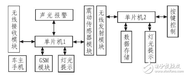
*Figure 1: Block diagram of the car anti-theft system*
**2. System Hardware Design**
**2.1 Host Control Module**
The host control module consists of a button, a power-on reset circuit, and a crystal oscillator circuit, as shown in Figure 2. It is responsible for processing sensor signals, managing the sound and light alarm, receiving data from the SPI transmitter module, and communicating with the TC35I GSM module via serial communication.
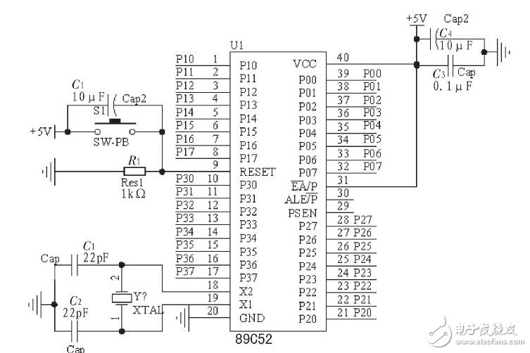
*Figure 2: Host Control Module*
**2.2 Vibration Sensor Module**
The circuit of the vibration sensor module is shown in Figure 3. When the vibration sensor is disturbed, contact piece S2 closes, causing the comparator U3A’s output terminal 1 to go low. This low signal is sent to the P3.0 port of the microcontroller, which then processes the signal accordingly.
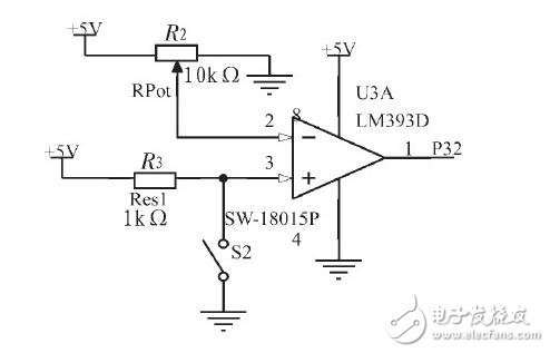
*Figure 3: Vibration Sensor Module*
**2.3 Sound and Light Alarm Module**
The sound and light alarm module circuit is shown in Figure 4. When the MCU outputs a high-level signal from the P1.6 port for 40 seconds, the ULN2003 inverter converts it to a low level, driving the buzzer and LED to flash.
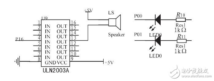
*Figure 4: Sound and Light Alarm Module*
**2.4 Remote Control Module**
The remote control module circuit is mainly composed of a microcontroller and a wireless transmitting module, as shown in Figure 5. When the alarm is triggered, the owner can remotely deactivate it using a remote control. Pressing K2 sends a low-level signal to the P3.2 port, triggering an interrupt program through the SPI interface. This sends a value of "1" to the wireless module, which is then received by the alarm device, stopping the alarm if an interrupt signal is received.
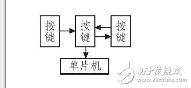
*Figure 5: Remote Control Circuit Flow Chart*
**2.5 GSM Alarm Module**
When the vibration sensor detects a low-level signal, the MCU communicates with the GSM module through the TXD and RXD serial interface. It sends AT commands to enable SMS sending or calling. The Siemens TC35I is a next-generation GSM module with RS232 interface, supporting data, voice, SMS, and fax transmission. It operates between 3.3–5.5 V and supports both 900 MHz and 1800 MHz bands.
**3. System Software Design**
The system software follows a modular design, including the main program, initialization subroutine, interrupt service routine, timer T1 setting, NRF2401 remote control transmission, GSM call, and alarm stop programs.
**3.1 Main Program**
The main program flow chart is shown in Figure 6. It begins with hardware initialization, configures the NRF2401 wireless receiving module to receive mode, and enters a low-power state. When the vibration sensor detects a signal, it triggers the sound and light alarm or a GSM call. These are two alarm modes, and the user can switch between them using a function key.
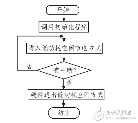
*Figure 6: Main Program Flow Chart*
**3.2 Initialization Procedures**
The initialization procedure is shown in Figure 7. It includes initializing the serial port, setting the I/O levels, configuring the NRF2401 for receive mode, initializing the GSM module, enabling interrupts, and setting up the serial communication.
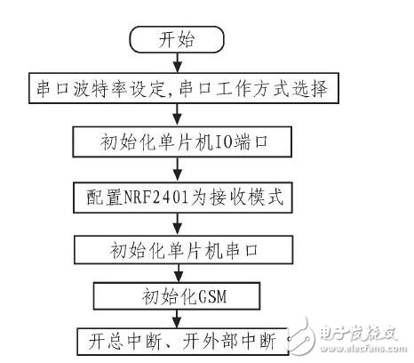
*Figure 7: Initialization Program Flow Chart*
**3.3 External Interrupt INT0 Service Program and Timer T0 Program**
The external interrupt INT0 service program and timer T0 program are shown in Figure 8. The INT0 service program detects the vibration sensor signal. Upon entering the interrupt, the total and external interrupts are disabled. If a low-level signal is detected, the timer T0 is started in 16-bit counting mode, timing for 1 second to control the LED flashing and buzzer alarm.
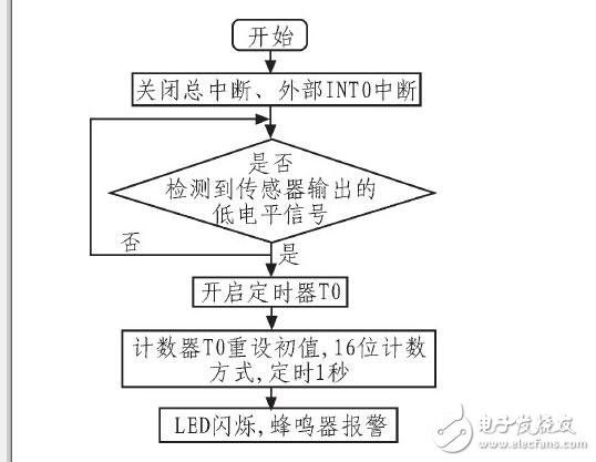
*Figure 8: External Interrupt INT0 Service Program and Timer T0 Program Flow Chart*
**3.4 NRF2401 Remote Control Transmission Program**
The NRF2401 remote control transmission program is shown in Figure 9. It configures the NRF2401 for transmit mode. When a button is pressed, the NRF2401 enters interrupt mode, packages the data, and communicates via SPI with the receiver module.
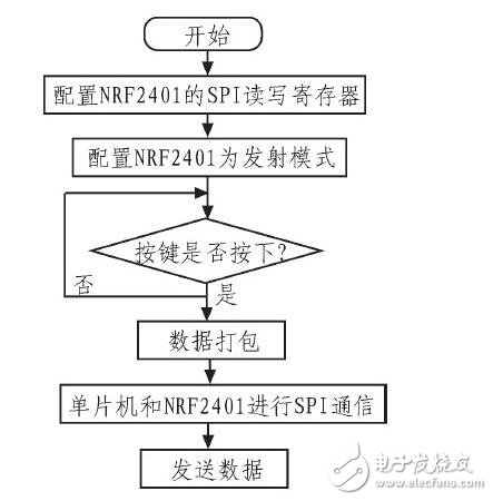
*Figure 9: NRF2401 Remote Control Transmitter Flow Chart*
**3.5 NRF2401 Remote Control Reception Program**
The NRF2401 remote control reception program is shown in Figure 10. The NRF2410 is configured for receive mode. When data is received, the timer stops, the LED turns off, and the buzzer stops, ending the communication.
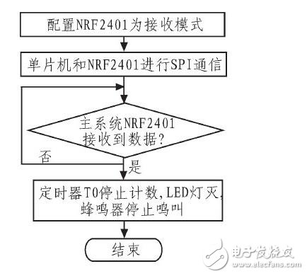
*Figure 10: NRF2401 Remote Control Reception Flow Chart*
**3.6 GSM Call Procedure**
The GSM call procedure is shown in Figure 11. It initializes the serial port, sets the working mode and baud rate, enables interrupts, and detects the sensor’s low-level signal. If detected, the MCU communicates with the GSM module via serial port using AT commands. If the handshake is successful, the MCU sends a call command to the GSM module, allowing the owner to receive the alarm call.
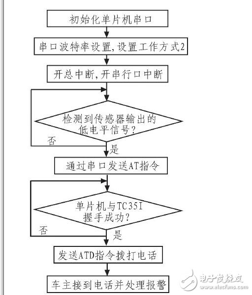
*Figure 11: GSM Call Procedure Flow Chart*
**4. Conclusion**
This car anti-theft alarm system uses the STC89C52 microcontroller as the main control unit, enabling real-time sound and light alarms and timely notifications to the owner via phone calls or SMS. Testing shows that the system can accurately activate and deactivate the alarm within a range of 0 to 70 meters. The cost of this system is kept under a few hundred dollars. It can be upgraded to work on 3G networks by replacing the communication module. If a camera is installed in the car, real-time images can be transmitted to the owner, providing strong evidence for future security monitoring.