Iso Room,Iso 8 Clean Room,Clean Room Standard,Clean Room Operating Costs Dongguan V1 Environmental Technology Co., Ltd. , https://www.v1airpurifier.com
Overview Environmental monitoring usually requires a small and flexible microcontroller. If a personal computer is used in such applications, it is a waste of its computing power and storage capacity. A dedicated microcontroller can be used to communicate with temperature, humidity sensors or other environmental monitoring sensors to read and store monitoring data . In order to achieve greater flexibility, these microcontrollers can be connected into a network, each uploading monitoring data to a more powerful system, and analyzing and recording the overall environmental parameters.
This application note describes how to use the MAXQ3210 low-power microcontroller to implement environmental monitoring applications. Adding a digital temperature sensor DS1822 that realizes power supply and communication through a 1-Wire® bus, we can build a battery-powered non-volatile temperature recording system with minimal components.
You can download the relevant demo code. The code is written in MAXQ assembly language and compiled in the standard macro assembly preprocessor and assembler that comes with the MAX-IDE development environment. This code is written for the MAXQ3210 evaluation board, so the following devices are also required (Figure 1). Temperature sensor: DS1822 economical 1-Wire digital temperature sensor (TO-92 package) RS-232 level converter: MAX233ACWP 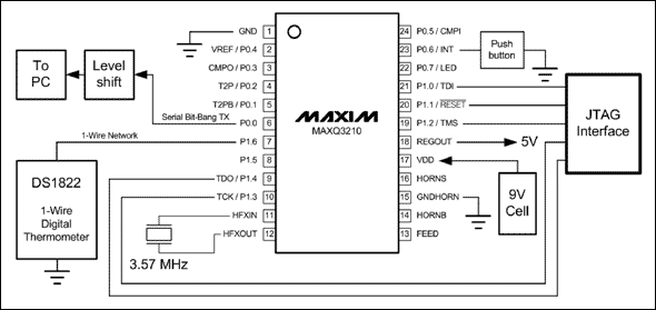
Figure 1. The MAXQ3210 1-Wire temperature recorder demonstration circuit requires component design target demo code to complete the following tasks (Figure 2): Communicate with the temperature sensor DS1822 through a 1-Wire network (bit analog mode). Wake up every minute to measure temperature. Store the temperature data in the non-volatile EEPROM inside the MAXQ3210. After power on, the temperature record data is sent through the bit analog serial port at a rate of 9600 baud. Convert temperature data to an easily recognizable ASCII format (decimal Fahrenheit) before sending. Clear the memory (erase the temperature data stored in the EEPROM) according to the host's requirements. 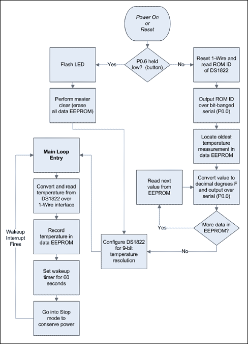
Figure 2. Flow chart of the temperature recording application. Why use the MAXQ3210? Almost all low-power MAXQ microcontrollers can achieve this application, but the MAXQ3210 is more suitable for temperature recording. Integrated voltage regulator. The MAXQ3210 integrates a 5V regulator and can be directly powered by a standard 9V battery. The MAXV3210's 5V regulated output can also power other devices (maximum current 50mA). This feature is very important, which means that if other devices can also use 5V power supply, there is no need to add a separate power chip. Low power consumption. The MAXQ3210 consumes very little current, and even at 3.58MHz full speed, the typical value is only 6mA. When the frequency is reduced or the processor stops working and enters the sleep state, the battery current can be lower. The integrated 8kHz ring oscillator in the MAXQ3210 drives a long-cycle wake-up clock, which can wake the processor from sleep after a programmable interval of up to 2 minutes. Internal data EEPROM. It is necessary to save the temperature record data when the power is turned off. These data may be collected for hours, days, or even weeks. The MAXQ3210 data storage space has 64 words of EEPROM, which can easily achieve this requirement. Each 16-bit word in EEPROM can be individually modified by calling a function in UTIlity ROM; EEPROM technology means that there is never an erase operation before writing data. If you need more EEPROM space, you can write data to any unused program EEPROM space. This writing process calls another function in UTIlity ROM to modify it word by word in a similar manner without reloading the entire application. 5V port pin. Like all MAXQ microcontrollers, the port pins of the MAXQ3210 can be flexibly set to input, output, weak pull-up, and tri-state. MAXQ3210 can also provide a variety of interface options. Because the port of the microcontroller is 5V level, it can be directly connected to 5V devices or connected to low-power devices through pull-up resistors (operating in tri-state / open-drain mode). Because this application requires few ports, using a large microcontroller will waste many functions. Piezo speaker driver. Although piezoelectric speaker functions are not used in this application, audible warning sounds are required in many types of environmental monitoring applications. For example, smoke monitoring and carbon monoxide monitoring. The MAXQ3210 can directly drive piezoelectric speakers, which can be achieved with very simple software. Only one control bit is needed to turn the piezoelectric speaker on or off. Depending on the selected speaker, the amplitude of the MAXQ3210 output can reach 100dB. Small package: The MAXQ3210 is available in a small 24-pin TSSOP package. Driving 1-Wire Networks Dallas Semiconductor / Maxim offers a range of sensors and other devices that use 1-Wire network interfaces. The data communication and power supply of this interface only need to add a data line and a ground wire, which means that the microcontroller only needs one port to communicate with the 1-Wire sensor.
The 1-Wire network works in a master multi-slave mode (multipoint network). The timing is very flexible, allowing the slave to communicate with the master at up to 16kbps. Each 1-Wire device has a globally unique 64-bit ROM ID, allowing the 1-Wire master to accurately select a slave located anywhere on the network for communication.
The 1-Wire bus works in open-drain mode. The master (or the slave that needs to output data) pulls the data line low to ground to indicate data 0, and releasing the data line to high indicates data 1. This is usually achieved by connecting a discrete resistor between the data line and VCC, but the MAXQ3210's port pins support weak pull-up mode. Simply switch the pin to weak pull-up mode and the data line can float high. Therefore, MAXQ3210 does not require external resistors. Since the master and slave only need to pull the data line low, and never actively pull the data line high, the data line can realize the "line-or" function, which prevents multiple slaves from trying to send through the 1-Wire bus at the same time There was a conflict with the data.
To drive the 1-Wire network, the MAXQ3210 uses software to implement the following types of time slots on a pin. Since all 1-Wire time slots are initiated by the master, there is no need to monitor the 1-Wire line when the MAXQ3210 is not communicating with the slave. For more detailed information about 1-Wire timing, please refer to the DS1822 data sheet. The reset slot width is about 1ms. In the first half of the time slot, the host (MAXQ3210) pulls the 1-Wire bus low, and then the host releases the bus to float high. All 1-Wire slaves on the bus reset and pull the bus low in the second half of the time slot. This step generates a presence pulse (online pulse), indicating to the master that one or more 1-Wire slaves are online and ready to start communication. The Write time slot is approximately 120 µs long. The master uses this time slot to send 0 or 1 to the 1-Wire slave. Both write time slots start with the host pulling the bus low for at least 1 microsecond. If a 1 is sent, the host then releases the 1-Wire bus (making it float high). If 0 is sent, the host keeps pulling the bus low for the rest of the time slot. The Read time slot is approximately 60µs long. The master uses this time slot to read the 0 or 1 sent by the slave. The time slot starts when the host pulls the bus low for at least 1 microsecond. The master then releases the bus, allowing the slave to pull the bus low (indicating 0), or releasing the bus to float high (indicating 1). The master samples the bus in the middle of the time slot to read the data sent from the slave. Since the MAXQ3210 is approximately equal to three and a half instruction cycles per microsecond (at 3.58MHz clock frequency), the software can use a port pin (P1.6) to easily implement the 1-Wire protocol. #define OWIN M0 [09h] .6; PI1.6 #define OWOUT M0 [01h] .6; PO1.6 #define OWDIR M0 [11h] .6; PD1.6 ;;;;;;;;;;;; ;;;;;;;;;;;;;;;;;;;;;;;;;;;;;;;;;;;;;;;;;;;;;;;;;;;;;;; ;;;;;;;;;;; ;;; FuncTIon: Reset1Wire ;; DescripTIon: Sends a standard speed 1-Wire reset pulse on P1.6 ;; and checks for a presence pulse reply. ;; Inputs: None ;; Outputs : C-Cleared on success; set on error (no presence ;; pulse detected) ;; Destroys: PSF, LC [0] ;; ;;;;;;;;;;;;;;;;;;;;; ;;;;;;;;;;;;;;;;;;;;;;;;;;;;;;;;;;;;;;;;;;;;;;;;;;;;;; Reset1Wire : move OWDIR, # 1; Output mode move OWOUT, # 0; Drive low move LC [0], #RESET_LOW djnz LC [0], $ move OWOUT, # 1; Snap high move LC [0], #SNAP djnz LC [0], $ move OWDIR, # 0; Change to weak pullup input move LC [0], #RESET_PRESAMPLE djnz LC [0], $ move C, OWIN; Check for presence detect move LC [0], #RESET_POSTSAMPLE djnz LC [0], $ ret ;;;;;;;;;;;;;;;;;;;;;;;;;;;;;;;;;;;;;;;;;;;;;;; ;;;;;;;;;;;;;;;;;;;;;;;;;;;;;; ;; Function: Write1Wire ;; Description: Writes a standard speed 1-Wire output byte on P1.6. ;; Inputs: GRL-Byte to write to 1-Wire. ;; Outputs: None. ;; Destroys: PSF, AP, APC, A [0], LC [0], LC [1] ;; ;;;;;;;;;;;;;;;;;;;;;;;;;;;;;;;;;;;;;;;;;;;;;;;;;;;;;;; ;;;;;;;;;;;;;;;;;;;;; Write1Wire: move APC, # 080h; Standard mode, select A [0] as Acc move Acc, GRL move OWDIR, # 1; Output drive mode move LC [1], # 8; 8 bits to write Write1Wire_slot: move OWOUT, # 0; Drive low for start of write slot move LC [0], #WRITE_PREBIT djnz LC [0], $ rrc; Get the next bit jump C, Write1Wire_one Write1Wire_zer move OWOUT, # 0; Keep the line low (zero bit) jump Write1Wire_next Write1Wire_one: move OWOUT, # 1 Write1Wire_next: move LC [0], #WRITE_POSTBIT djnz LC [0], $; Finish the time slot move OWOUT, # 1; Drive back high (end of slot) move LC [0], #WRITE_RECOVERY djnz LC [0], $; Recovery time period djnz LC [1], Write1Wire_slot ret The function of realizing read slot is similar. Note that all data on the 1-Wire bus is sent least significant bit (LSB) first.
When using the MAXQ3210 to implement 1-Wire timing, another point to note is that although the resistance of the 1-Wire bus pull-up resistor is related to the number of devices on the bus, it is usually between 4kΩ and 5kΩ. However, the weak pull-up resistor on the MAXQ3210 port pin is 50kΩ to 100kΩ. In order to prevent the 1-Wire bus from changing from low to high for too long, the demo code first sets the P1.6 output to a short high level, forcibly pulls the bus high, and then becomes a normal weak pull-up mode. As long as the process is not performed when the slave tries to pull the bus low, there will be no problems. In addition, a separate pull-up resistor can be added to the bus, so that the port output low can represent 0 in a normal way, and the output tri-state represents 1.
Note: When the built-in 1-Wire network has a long transmission distance or a large number of connected slaves, other matters need to be noted. For more information, please refer to the following application notes. AN148: 1-Wire Network Reliable Design Guide AN937: Book of iButton Standards Measure Temperature with DS1822 Although the MAXQ3210 can use the above code to communicate with most 1-Wire slave devices, in this application we will mainly consider communicating with the DS1822. DS1822 is a 1-Wire slave device that can measure 9 to 12-bit Celsius temperature, and the measurement results can be read by the 1-Wire master. Like most 1-Wire slaves, the DS1822 can be powered entirely by the 1-Wire bus, which we call parasitic power supply.
The DS1822 has a measurement range of -55 ° C to + 125 ° C and is suitable for most indoor and outdoor temperature measurement applications. The temperature resolution is 0.5 ° C at 9 digits and 0.0625 ° C at 12 digits. The time required for a temperature conversion is about 94ms at low resolution and about 750ms at the highest resolution. Since this is a simple application, we choose 9-bit resolution and ignore the lowest bit (0.5 ° C). This allows the entire 8-bit signed temperature data to match the MAXQ3210's 8-bit accumulator.
All 1-Wire slave devices support a common instruction set, so that the master can determine the number of slaves on the bus, read the ROM ID, and can communicate with a slave or a group of slaves. Once a 1-Wire slave is activated, the master can send special commands to that slave type. All other slaves that have not been activated are in a wait state, and do not start monitoring the 1-Wire bus again until the next reset pulse appears.
Since there is only one 1-Wire device on the bus in our application, we can use the simplest instruction set to access the slave device without reading the slave's ROM ID. When there are multiple slave devices on the bus, the ROM ID is used to distinguish different slave devices. The ROM ID of the DS1822 was also read once in our program, but only for demonstration.
We will use the following 1-Wire instruction set. For other instructions supported by DS1822, please refer to its data sheet. Read ROM [33h]. This instruction assumes that there is only one slave device on the 1-Wire bus. After receiving this command, the 1-Wire slave sends its 8-byte ROM ID back to the 1-Wire master. This ID includes a 48-bit serial number, 8-bit CRC, and 8-bit family code. The family code represents the device type. The family code of DS1822 is 22h. After receiving the Read ROM command, the 1-Wire slave is activated and responds to subsequent commands related to the slave device. Skip ROM [CCh]. This command can be used when there are one or more slave devices on the 1-Wire bus. This command activates all slaves on the bus, regardless of the ROM ID of the slave. When there is only one slave on the bus, this command can be used to activate the slave without reading the slave ID, so that it can receive subsequent related instructions. When there are multiple slaves on the bus, if this instruction is used, it must be ensured that the following instructions will not cause the slave to send data to the master. Because the slave may send different data and cause data conflict. Write Scratchpad [4Eh]. This is a DS1822 specific instruction. Before using the Read ROM or Skip ROM instruction to activate the device. After this command, the 1-Wire master sends 3 bytes of configuration data to configure the DS1822, including the bit resolution of the temperature conversion. For more details, please refer to the data sheet of DS1822. Read Scratchpad [BEh]. This is also a DS1822 specific instruction, which allows the host to read up to 9 bytes of data from the DS1822. These data include the configuration register value set by the Write Scratchpad command, and the most recent temperature conversion result. For more details, please refer to the data sheet of DS1822. Our application only needs the first two bytes, which are the most recent temperature conversion results. Convert Temperature [44h]. This is a DS1822 specific instruction. DS1822 starts to measure the temperature after receiving this instruction, and converts it into digital quantity according to the specified bit resolution. The result is stored in two internal registers, and the 1-Wire master can be read by Read Scratchpad. When executing the Convert Temperature command, the DS1822 needs to consume more current (up to 1.5mA), which may exceed the current that the 1-Wire bus weak pull-up can provide. Therefore, once the host issues this command, the 1-Wire bus must be strongly pulled up until the temperature conversion is complete. During this period, no communication can take place on the 1-Wire bus. The MAXQ3210 simply meets this requirement by switching the P1.6 port from a weak pull-up to an output high level. The MAXQ3210 port driver can output enough current to operate the DS1822. ;;;;;;;;;;;;;;;;;;;;;;;;;;;;;;;;;;;;;;;;;;;;;;;;;;;;;;; ;;;;;;;;;;;;;;;;;;;;;;;; Function: ConvertAndReadTemp ;; Description: Sends commands to measure temperature and read ;; scratchpad from the DS1822. ;; Inputs: None. ;; Outputs: GRL-8-bit signed temperature value, in degrees C. ;; Destroys: PSF, AP, APC, A [0], A [1], A [2], LC [0], LC [1 ] ;;;;;;;;;;;;;;;;;;;;;;;;;;;;;;;;;;;;;;;;;;;;;;;;;;;;;; ;;;;;;;;;;;;;;;;;;;;;; ConvertAndReadTemp: call Reset1Wire; Reset the DS1822 move GRL, #OW_SKIP_ROM; Select the DS1822 call Write1Wire move GRL, #OW_CONVERT; Send temp convert command call Write1Wire move OWDIR, # 1; Turn on strong pullup for draw current move OWOUT, # 1 move LC [0], # 55; About a second delay: move LC [1], # 0 djnz LC [1], $ djnz LC [0], delay call Reset1Wire; Conversion completed; reset again move GRL, #OW_SKIP_ROM; Select again call Write1Wire move GRL, #OW_RD_SCRATCH; Read the scratchpad values ​​call Write1Wire call Read1Wire move A [1], GRL; Temp LSB 3210xxxx call Read1Wire move A [2], GRL; Temp MSB sssss654 move Acc, A [1]; 3210xxxx and # 0F0h; 3210 ---- xchn; ---- 3210 move A [1], Acc move Acc, A [2]; sssss654 and # 00Fh; ---- s654 xchn; s654 ---- or A [1]; s6543210 move GRL, Acc ret Store the measurement results in the data EEPROM To prevent accidental data errors on the 1-Wire bus, the demo code Each measurement performs three temperature conversions (A, B, and C), and selects a result to store. The selection basis is: If all data are the same, store the data. If two of the three data are the same (A = B, B = C or A = C), then select the same data storage. If no data is the same, the intermediate value is stored. For example, if (A> B> C), store B. The selected value is written to a word in the data EEPROM. Since the sampling result is one byte, the high byte of each word is used to indicate whether the record (ie, word) is empty. If the high byte is 0, the record / word is empty, and if the high byte is not 0, the low byte is valid temperature data. In this way, it is possible to distinguish between null records and stored data with valid data at 0 ° C. ;; Two out of three majority vote, or failing that, the measurement ;; in the middle of the three. Move Acc, A [4] cmp A [5] jump E, recordTempA; If (A == B), use that value cmp A [6] jump E, recordTempA; If (A == C), use that value move Acc, A [5] cmp A [6] jump E, recordTempB; If (B == C), use that value move Acc, A [4] sub A [5] jump S, B_greaterThan_A; Sign is set if (AB) is negative ;; If (A> B) {;; If (C> A) record A (C> A > B) ;; If (B> C) record B, (A> B> C) ;; else record C (A> C> B) A_greaterThan_B: move Acc, A [4] sub A [6]; AC jump S, recordTempA; Sign is set if (AC) is negative move Acc, A [5] sub A [6]; BC jump S, recordTempC; Sign is set if (BC) is negative jump recordTempB ;; If (B> A ) {;; If (C> B) record B (C> B> A) ;; If (A> C) record B, (A> B> C) ;; else record C (B> C> A) B_greaterThan_A : move Acc, A [5] sub A [6]; BC jump S, recordTempB; Sign is set if (BC) is negative move Acc, A [4] sub A [6]; AC jump S, recordTempC; Sign is set if (AC) is negative jum p recordTempB recordTempA: move GRL, A [4] jump recordTemp recordTempB: move GRL, A [5] jump recordTemp recordTempC: move GRL, A [6] jump recordTemp recordTemp: move A [15], GRL move GRL, # '@ 'call TxCharBB move GR, DP [0] move GRL, GRH call TxHexByteBB move GRL, DP [0] call TxHexByteBB move GRL, #' 'call TxCharBB move GRL, #' W 'call TxCharBB move GRL, A [15] call TxHexByteBB move GRL, A [15]; Low byte contains temp data move GRH, # 055h; High byte marks nonzero entry lcall UROM_loadData; Write entry to data EEPROM call IncDP0_EE; Move to the next entry position move GR, # 0000h; Erase any data that exists lcall UROM_loadData; Erase the oldest entry The record is cyclic, starting from the data EEPROM address 020h to 05Fh, and then back to the beginning. Each time a new record is written after that, the oldest record will be erased. When sending data out through the serial interface, the application locates the oldest recorded data by looking for whether there are empty records in front. Saving power consumption Because this application only records temperature data once per minute, it only takes a few seconds to read the DS1822 data and store it in the EEPROM. Most of the time the application is waiting for the one minute delay to end. According to the requirements of the application, the temperature recording interval can be lengthened without changing too many codes, for example, to five minutes, ten minutes or thirty minutes. In order to reduce the battery consumption during the waiting period, the power consumption should be reduced as much as possible.
The lowest power mode that the MAXQ3210 can provide is standby mode. In this mode, the program stops running, the high-frequency crystal oscillator stops working, and the current drops to the order of microamps. Since no other devices are still working, we need to periodically wake up the MAXQ3210 from standby mode to measure the temperature.
This requirement can be achieved by the wake-up clock of the MAXQ3210. This clock operates on an internal 8kHz low-current ring oscillator that is still operating in standby mode and can wake up the microcontroller at programmable intervals of up to two minutes. This timed wake-up is ideal for our application. In the application, the "alarm clock" can be set to one minute. After the microcontroller finishes working, it then enters the standby mode to save power consumption, and then waits to be awakened to collect data again. ;; Start the wakeup timer for 60 seconds. Move CKCN.6, # 1; Select ring oscillator mode waitRing: move C, CKCN.5 jump NC, waitRing; Wait for RGMD = 1 (running from ring) move WUT, # 30000 ; 1 / 8kHz * 30000 * 16 = 60 seconds move WUTC, # 0101b; Start the wakeup timer (running from ring) move IV, #wakeUpInt; Set interrupt handler for wakeup interrupt move IMR.0, # 1; Enable interrupts from module 0 move IC.0, # 1; Globally enable interrupts move PD0.7, # 0; Turn off output mode for LED pin move PO0.7, # 1; Return to default state (weak pullup) move CKCN.4, # 1 ; Go into Stop mode, wait for wakeup int nop jump mainLoop; Back for another round ;;;;;;;;;;;;;;;;;;;;;;;;;;;;;;;;;; ;;;;;;;;;;;;;;;;;;;;;;;;;;;;;;;;;;;;;;;;;;;;;;;;;; wakeUpInt: move PD0. 7, # 1; Turn on output mode for LED port pin move PO0.7, # 0; Light the LED move CKCN.6, # 1; Select ring oscillator mode wakeUp_ring: move C, CKCN.5 jump NC, wakeUp_ring; Wait for RGMD = 1 (running from ring) move LC [0], # 4000 djnz LC [0], $ move PO0.7, # 1 ; LED off move LC [0], # 4000 djnz LC [0], $ move WUTC, # 0; Clear wakeup timer flag move CKCN.6, # 0; Select crystal mode wakeUp_xtal: move C, CKCN.5 jump C, wakeUp_xtal; Wait for RGMD = 0 (running from crystal) move GRL, # 'W' call TxCharBB move GRL, # 'U' call TxCharBB move GRL, # 0Dh call TxCharBB move GRL, # 0Ah call TxCharBB reti upload temperature record data per After power-on reset, the application sends temperature record data to the host system. Data is sent at a rate of 9600 baud through a 10-bit asynchronous serial interface (1 start bit, 8 data bits, 1 stop bit). The MAXQ3210 does not have a hardware UART serial port and needs to be implemented using a port pin simulation. Because this application only needs to send, no need to receive, so it is relatively simple to implement. ;;;;;;;;;;;;;;;;;;;;;;;;;;;;;;;;;;;;;;;;;;;;;;;;;;;;;;; ;;;;;;;;;;;;;;;;;;;;;; ;; Function: TxCharBB ;; Description: Transmits a 10-bit serial character (bit-banged) ;; over P0.0.; ; Inputs: GRL-Character to send ;; Outputs: None ;; Destroys: PSF, AP, APC, A [0], LC [0], LC [1] ;;;;;;;;;;;;; ;;;;;;;;;;;;;;;;;;;;;;;;;;;;;;;;;;;;;;;;;;;;;;;;;;;;;;; ;;;;;;;; TxCharBB: move APC, # 080h; Standard mode, select A [0] as Acc move Acc, GRL move PO0.0, # 0; START bit low move LC [0], #BITLOOP djnz LC [0], $ move LC [1], # 8; 8 bits TxCharBB_bitLoop: rrc; Get the next bit jump C, TxCharBB_one TxCharBB_zer move PO0.0, # 0 sjump TxCharBB_next TxCharBB_one: move PO0.0, # 1 TxCharBB_next: move LC [0], #BITLOOP djnz LC [0], $ djnz LC [1], TxCharBB_bitLoop move PO0.0, # 1; STOP bit high move LC [0], #BITLOOP djnz LC [0], $ move LC [0], #BITLOOP djnz LC [0], $ ret To convert temperature data from a signed binary, 8-bit Celsius value to an easily recognizable ASCII code, Fahrenheit value, more codes need to be added, but These codes Single understandable. Use the BCD (Binary Coded Decimal) arithmetic rule to perform the binary to decimal conversion, while completing the conversion from Celsius to Fahrenheit. move GR, @DP [0]; Get the current entry move Acc, GRH; Check the high byte jump Z, endOutput; If it's zero we're done move A [15], GRL; Save the low byte (temp value) move A [7], # 0; Hundreds = 0 move A [6], # 0; Tens = 0 move A [5], # 0; Ones = 0 move A [4], # 0; Tenths = 0 move A [3], # 0; Add 01.8 per degree C move A [2], # 1 move A [1], # 8 move Acc, A [15]; s6543210 jump S, tempNegC tempPosC: move GRL, # '+' jump Z, tempPrint move LC [0], Acc tempPosC_loop: call AddBCD djnz LC [0], tempPosC_loop move A [3], # 3 move A [2], # 2 move A [1], # 0; Add 32.0 call AddBCD jump tempPrint tempNegC: move GRL, # '-' neg jump Z, tempPrint; Negative zero jump S, tempPrint; -128 is outside the sensor range anyhow move LC [0], Acc tempNegC_loop: call AddBCD djnz LC [0], tempNegC_loop move A [3], # 3 move A [2], # 2 move A [1], # 0; Subtract 32.0 call SubBCD jump NC, tempPrint move GRL, # '+'; Back to positive again jump tempPrint tempPrint: call TxCharBB; Print plus / minus sign call TxTempBB; Print temperature valu e + newline call IncDP0_EE; Move to the next entry Because the port output of the MAXQ3210 uses a 5V level, an external device (such as MAX233ACWP) must be used to level shift the output before connecting to the COM serial port of the PC. After completing this conversion, you can use any standard terminal emulation program to receive the data output by the application. RST DS1822 Detected: 22A9CC15000000E5 + 57.2 + 57.2 + 57.2 + 57.2 + 57.2 + 57.2 + 57.2 + 57.2 + 57.2 + 59.0 + 62.6 + 69.8 + 59.0 + 55.4 + 55.4 + 55.4 + 55.4 + 55.4 + 55.4 + 55.4 + 57.2 + 55.4 + 55.4 + 57.2 + 57.2 + 57.2 + 57.2 + 57.2 + 57.2 Application function expansion The MAXQ3210 has 1k x 16 (1024 words) of EEPROM program storage space, and the demo code only occupies 60% to 70% of it. The application code can be further optimized so that it only occupies 50% of the program storage space. After the core functions of the application are developed, many additional functions can be added to make it a fully functional environment detection system. Multiple sensors. The 1-Wire subroutine can be easily expanded to enable access to multiple DS1822 temperature sensors. These sensors can be connected to separate ports (one device per port), or a group of devices can be hung on a single wire (multiple Point configuration). The multi-point configuration structure is more complicated, but it enables the MAXQ3210 to connect more devices. Multiple sensor types. Applications can connect many different types of 1-Wire sensors to measure different environmental parameters, including: humidity (DS1923 temperature / humidity recorder), physical switch (DS2401 silicon serial number), or use an analog-to-digital converter (DS2450, 1 -Wire interface, four-channel, A / D converter) universal sensor. For more information, see the 1-Wire / iButton® product page on the Maxim IC website. Audible alarm. The MAXQ3210 has a built-in piezoelectric speaker drive circuit, so it is very simple to add high-decibel speakers. When the temperature conversion result is higher or lower than the specified threshold, an alarm will sound. Increase the recording capacity. Applications can write data to unused program EEPROM in the same way as data EEPROM. If the application code is small enough, a part of the program EEPROM can be used to store more temperature conversion results, and then record longer temperature data. Two-way serial communication. Implementing a bidirectional serial port through bit emulation is more complicated than just implementing a transmit port, but the MAXQ3210 can still be easily implemented. With a bidirectional port, the host can request the MAXQ3210 to upload recorded data, set configuration data (such as the temperature resolution of the DS1822), access specific sensors as needed, and even update the MAXQ3210's firmware via the serial interface. Conclusion The small package, low power consumption, and flexible I / O of the MAXQ3210 are ideal for battery-powered environmental monitoring applications. Many 1-Wire sensors can be used to measure environmental parameters such as temperature and humidity, and these sensors can also interface with the MAX3210 through only one port. Finally, the data can also be stored in the non-volatile EEPROM memory of the MAXQ3210 for later query and analysis.
Using MAXQ3210 to build a 1-Wire temperature recorder
Abstract: This application note describes how to use the microcontroller MAXQ3210 and the 1-Wire digital temperature sensor DS1822 to build a temperature recorder. The temperature data is recorded in the EEPROM inside the MAXQ3210 for subsequent download and analysis.