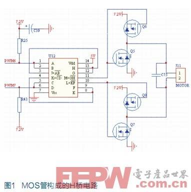
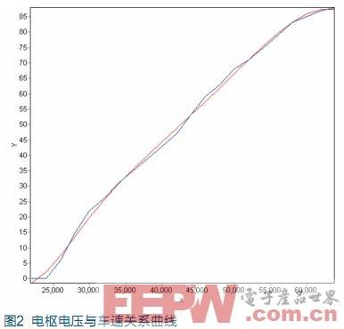
Design and Implementation of Intelligent Vehicle Speed ​​Control System In the smart car competition, the speed control cannot use pure PID, but must adopt a "multi-mode" speed control algorithm that can smoothly switch between multiple modes such as full acceleration, emergency braking and closed-loop control, in order to adapt to different road conditions Quickly and accurately change the vehicle speed to achieve a stable corner. System hardware design According to the competition requirements, the intelligent car speed control system designed in this paper, taking Freescale MC9S12DG128 single-chip as the core [1], together with the vehicle speed detection module, DC motor drive module, power supply module, etc., constitutes an intelligent vehicle speed closed-loop control system. The single chip microcomputer adopts a reasonable control algorithm to control the vehicle speed according to the track information. The vehicle speed detection uses a photoelectric encoder installed on the rear axle of the car model. The DC motor drive uses an H-bridge circuit composed of four MOS tubes. , The power supply module supplies power to the single-chip microcomputer, photoelectric encoder and drive motor. System modeling To design a control system for actual objects, the first thing to do is to model the actuator and the system, and calibrate the input and output of the system. In order to design an appropriate controller for the vehicle speed control system, it is necessary to order and normalize the speed system [2]. To this end, the experiment of measuring acceleration and deceleration models were designed separately. The motor speed is measured by a photoelectric encoder attached to the rear axle of the car model. The gear ratio of the encoder gear to the drive wheel is 33/76, and each pulse output by the encoder corresponds to a smart car movement of 1.205mm. The car model can be adjusted by adjusting the duty cycle of the PWM wave added to the motor. The PWM module on the single-chip microcomputer can be 8-bit or 16-bit. In order to improve the speed regulation accuracy, the motor speed regulation module selects 16-bit PWM, and its duty cycle adjustment range is from 0 to 65535, corresponding to the motor armature voltage from 0% to 100% battery voltage. Place the car model on a long straight track, and apply different voltages to the drive motor in an open loop, and record the speed value of the car model after the speed has stabilized. Then, the curve of fitting the measured armature voltage with the vehicle speed is shown in FIG. 2, and the smart car acceleration model can be approximated as a linear model from FIG. 1. According to the experimental data, the zero point and gain of the vehicle speed actuator system can be determined. The relationship between vehicle speed V and duty cycle PWM_RaTIo is shown in Equation 1: V = PWM_RaTIo × 402 + 22000 (1) Among them: The value range of PWM_RaTIo is 0-65535 There are three methods for car deceleration: free deceleration, energy consumption braking and reverse connection braking. Free deceleration power comes from frictional resistance, which is basically considered constant. Energy consumption braking consumes energy to the internal resistance of the motor. The braking force decreases as the vehicle speed decreases, and the acceleration can also be reduced faster by control. Reverse connection braking is realized by applying reverse voltage, and the braking force is related to the applied reverse voltage. Due to the limited grip of the tire, the tire may slip after the braking force exceeds a certain value. Once skidding occurs, the braking distance will become longer and the corner radius will become larger. If the braking force can always be controlled at the critical slip point, the shortest braking distance can be obtained. Among the three deceleration methods, only reverse braking can give different reverse braking forces according to different vehicle speeds, allowing the vehicle speed to decrease with the maximum slope. Therefore, through a large number of experiments, the maximum braking voltage without slipping was determined, and the maximum duty cycle of the non-slipping stroke was about 55,000. Because there will be differences in different tracks, there is a margin in programming. Use shock as a sign to identify whether the car model is slipping when braking. You can take several typical vehicle speeds, let the car model increase to the preset speed on the straight, and then use a set of reverse connection voltages to perform reverse connection braking, observe and record the highest non-slipping brake voltage. In this way, each typical vehicle speed has a corresponding maximum braking voltage. After comparing the maximum non-slip reverse connection voltage with the vehicle speed, it is found that the maximum non-slip reverse connection voltage is proportional to the vehicle speed. Consider the model of a DC motor. When an external voltage is applied to the armature of the motor, the rotor of the motor starts to rotate, generating a back EMF. This voltage is proportional to the speed of the vehicle. When the back EMF generated on the rotor is equal to the applied voltage, the motor speed reaches a steady state. Therefore, the remaining voltage after the reverse braking voltage minus the back EMF generated by the motor is used for deceleration. When the car model is to decelerate, you can first calculate the back EMF of the rotor from the current vehicle speed, and then superimpose a reverse connection braking voltage on this basis and send it to the actuator. The resistance of the car model is mainly divided into ground sliding friction and wind resistance, and the quality of the car model remains constant during driving. In the case of low vehicle speed, the wind resistance can also be regarded as a constant value. According to the above experimental data and reasoning, the main part of the vehicle speed model is the first-order inertial link. Speed ​​control strategy After analysis, the track is roughly divided into straight roads, curves of 90 degrees and above, and S-shaped curves. To achieve maximum speed on different roads, the key question is how to determine the condition of the road. The following are Judging conditions and passing strategies for several roads. a. Straight judgment conditions and passing strategies When the car detects a black line in the detection range of the three photoelectric cells in the middle, it is considered that the car is driving on a straight road. If the condition of the straight road is met, the car is accelerated until the brake condition is satisfied when it is added to a larger value. If a black line is detected for dozens of consecutive cycles, it means that the car is driving on a long straight and the brakes are needed when turning. Straight maximum speed is the maximum speed that the car does not rush out of the curve when entering from a long straight. The car can't be higher than this speed when driving. Of course, the more timely and sensitive the brakes, the greater the speed on the straight. The experiment obtained is about 55000 (corresponding to the duty ratio of PWM). The minimum speed required to brake is the maximum speed that allows the car to enter a curve from a long straight, and can smoothly pass the curve when the brake is not used. When the instantaneous speed of the car is higher than this speed when entering a corner, the brake is activated, otherwise, the brake is not used. Experiments have measured that the maximum speed of a long straight entering a corner does not exceed 50000 (corresponding to the duty cycle of PWM). b. Curve judgment conditions and passing strategies When the car does not meet the conditions of a straight road, it drives on a curve. Due to the difference in curvature radius and angle of the curve, it is divided into 90 degrees and more than 90 degrees and S-shaped curves. When the car is driving in a curve, only one side of the sensor continuously detects the black line, and then the angle of the curve is determined according to the length of time the sensors on both sides detect the black line; if the car is driving on an S-shaped curve, the sensor The detected value will continuously change within the horizontal deviation range. In short, on a curve, you must drive at the maximum speed of the curve. The maximum speed of the curve is to let the car accelerate on the curve until it rushes out of the track. When the speed of the car on the curve is less than the maximum speed of the curve, the duty cycle of the PWM signal must be adjusted to gradually accelerate the car. The experiment measured that the maximum speed of all corners does not exceed 32000 (corresponding to the duty cycle of PWM). c. Cross line recognition According to the rules of the game, there is also a cross line, but since it crosses at a right angle, it is only necessary to keep the original direction and speed of the progress when multiple sensors detect the black line. Conclusion The national smart car competition ultimately compares speed. To achieve good results, the car can be driven at the limit speed on different roads. Through a large number of experiments, the limit speed parameters of the car on different shapes of roads are obtained, and the appropriate parameters are selected according to the judgment conditions of different roads, and then the PWM is adjusted according to the speed value, so as to achieve fast and stable patrol driving of the smart car.
Children or Kids Headphones are specially designed for children over 3 years old. The biggest difference from ordinary headphones is hearing protection. The maximum decibel value is limited to 85dB.
Advantages:
1. Protect children's hearing, 85dB maximum volume.
2. Strange style, including a variety of cartoon design.
3. The color is bright and cool, and it is very popular among children.
4. Comfortable to wear.
Wireless Earphones,Kids Earphones,Childrens Headphones,Kids Wireless Headphones Shenzhen Linx Technology Co., Ltd. , https://www.linxheadphone.com