Design of wireless sensor network based on structured method The wireless sensor network (WSN) is composed of independent, fully embedded, small-volume, low-power nodes that can detect data from or control the target environment and communicate with each other wirelessly. Detection and control are done through interconnected sensors and actuators, and these sensors and actuators are managed either remotely or through embedded applications. The number of these nodes varies from a dozen to thousands. A typical system consists of hundreds of nodes distributed throughout the building or outdoor space. Many wireless sensor networks use private standards to implement wireless networking, but the recent trend is gradually toward standardized low-power wireless communications. ZigBee based on the well-known 802.15.4 specification is a standard for wireless detection and control. Although the 802.15.4 document only describes the PHY and MAC layers of the protocol, ZigBee built on 802.15.4 also provides network and application layer specifications. ZigBee has many advantages, including a grid protocol that can implement multi-hop routing and data transmission, security specifications, and a complete set of parameter settings for application layer interoperability. In short, ZigBee provides embedded application developers with a higher level of abstraction for managing networks and connecting other nodes. Although this article mainly discusses ZigBee, many of its views and conclusions are also applicable to other standards that use 802.15.4 MAC and PHY. To avoid confusion, the following assumes that our target design involves a multi-hop network that uses mesh routing protocols, 802.15.4 compatible modulation schemes, and media access protocols. This article also assumes that the reader has a basic understanding of the ZigBee and 802.15.4 specifications. Network organization and scale Network organization and scale are perhaps the most important design options. It often informs and guides the subsequent design process. It also has constraints because large networks are often more difficult to design and maintain. Fortunately, there are now ways to easily implement and maintain very large networks. The most advanced ZigBee network is currently between 300 and 500 nodes. This scale does not seem large, but imagine that all these nodes work on the same physical channel, send data to each other at the same time, route the data according to the behavior of each node, and try to maintain the integrity of the entire network at the same time (through Send periodic control messages), this should be a very noisy and crowded network. It should also be noted that the 802.15.4 specification based on the ZigBee standard uses the CSMA / CA (Carrier Sense Multiple Access / Collision Avoidance) protocol, which means that no two nodes can be simultaneously “in the hearing†range. speak". If you "talk" at the same time, you will encounter communication failure, you must delay and try again. If the network is already congested, these retries will cause cascading transmission failures, and more and more nodes attempting to initiate air access will increase the channel congestion. In fact, one of the main challenges when designing a network with more than hundreds of nodes is how to effectively manage network congestion (another challenge is to optimize system resources used to store internal stack state at runtime). The following subsections will briefly introduce three different strategies for solving congestion problems. Network density Obviously, the "300-node network" provides us with very little information about network organization. Due to the above-mentioned collision and collision problems, network density is also an important factor that affects the health of the network, that is, how many nodes are present in the listening range of each node, or in other words, how many other nodes can be heard by an ordinary node? Expert recommendations are less than 5, because this number supports redundant designs and relatively non-blocking communication media. A network with more than 7 nodes is likely to have severely congested network segments and increase the burden on the network. A related question ensues, how can a system designer determine how many nodes can be heard? An obvious strategy is to customize embedded applications. Information about neighboring nodes is actually an important part of the protocol operation in the ZigBee network. In fact, the nodes will actively broadcast their own information, and this information will be received by every other node within the effective range. Adjacent tables can be queried by the resident program and count the number of unique entries. The resident program then sends this diagnostic result to the designated node. Obviously, this only makes sense during network installations where the network density can still be changed. Once the network is installed and operational, the density information will act as a consultant in the troubleshooting process. Please note that if the size of the adjacent table is smaller than the number of surrounding nodes, the ZigBee stack will force the periodic withdrawal of table entries. This revocation may also negatively affect the overall network performance, because even if no nodes in the path are offline, the route will be forced to be rediscovered. Therefore, in addition to limiting the network density to avoid congestion, the network density must also be determined according to system resources (such as the size of adjacent tables). In the case where the physical location of the node is fixed due to application requirements, the network density can be easily controlled by reducing the output power of the transceiver in the congested area. In theory, reducing the output power and increasing the distance between nodes to make them less likely to hear each other have the same effect. Manufacturers tend to set the output power to the maximum value to ensure the maximum operating range and the best link quality. According to our experience, in indoor applications where distance performance is not important, the output power can be easily reduced. According to experience, the output power is reduced by 3dBm, and the effective distance range can be shortened by 1.5 times. The final consideration for density is that the failure rate is increased high enough to trigger the theoretical limit of the above cascading failure effects. Of course, this parameter depends on the amount of information sent by the application itself. According to experience, if each node sends a maximum length of data packets per second, then this limit is about 25 nodes within the listening range of each node. The density limit seems to be constant, regardless of the stack implementation, which means that the density limit is related to the more basic CSMA operation of the MAC layer. For example, we can infer that the density limit of a node that sends a packet every n seconds is to multiply the maximum density by 1.2n. This approximation should never be used as an accurate guideline for network density, because the actual value will depend on the ratio of routers and end devices in the network. Network division according to channel When nodes cannot be deleted or the output power cannot be reduced, the system designer can choose to divide a single network working on a single channel into multiple networks working on different channels to solve the network congestion problem. 802.15.4 specifies 16 channels in the 2.4 GHz frequency range, and an additional 10 channels are added in the 900 MHz frequency range. Placing the network on different channels can completely isolate the mutual influence between different networks, but each network may need to use a coordinator (coordinator) and connect these coordinators as required, which brings additional complexity. If the network to be divided is already logically separated, the method of dividing the network according to the channel is the most effective. For example, in building automation applications, it is usually ideal to let each floor's network work on its own channel. But if there is a network coordinator on each floor, it is troublesome for the nodes between different floors to communicate with each other, especially if this is done, it may affect the network performance (this is the case with high-density networks). Similarly, it can also be divided according to the room or office area. The most important thing is that the decision to divide the network according to physical channels should be made according to the specific application requirements and the number of available channels. When nodes in multiple sub-networks need to communicate with each other, this division also makes the overall design more complicated. The channel mask (just like the transceiver output power) is a configurable network parameter. The application engineer can assign a suitable channel mask to the network coordinator and network devices that must establish a connection with the coordinator. As a standard step, the coordinator will perform an energy detection scan to pick out the "least active" channel from the channel mask. It is worth noting that there is no other way to force the coordinator to work on a specific channel except for assigning a single channel to the mask. However, it is strongly recommended to maintain at least two channels in the channel mask, because in-band interference from WiFi networks, Bluetooth headsets, and other electronic devices can temporarily occupy a specific channel that is otherwise idle, causing the entire network to be paralyzed. Leaving multiple channels in the channel mask not only provides the coordinator with room for channel selection, but also allows it to flexibly switch to a channel with lower congestion in the future. Network division based on PANID The last strategy is to divide the network according to PANID. The efficiency of this method is generally recognized to be lower than that based on the physical channel. PANID is a unique identifier known to all devices in a given network. Devices using different PANIDs cannot communicate, allowing multiple networks to coexist in the same area, and data from one network will not appear on another network. In fact, multiple networks with different PANIDs can use the same physical channel to communicate with each other. Although splitting the network according to PANID does not affect the degree of air congestion, the amount of processing overhead at each node can be reduced by filtering out traffic from neighboring network devices (with another PANID) at the lower layer of the stack. In most cases, filtering can be done automatically by the PHY layer hardware, thereby freeing up more application resources and time. For applications where application processing and routing overhead dominate, the method of partitioning based on PANID can efficiently accommodate more nodes in a given area. One benefit of PANID-based segmentation is that there are relatively many possible unique segments, up to 216 accurately. Although there are only 26 physical channels, PANID provides a more flexible method for segmentation, although it is less efficient. Most wireless systems will use a combined strategy of PANID segmentation and channel number segmentation. In short, this combination strategy can provide the best flexibility and efficiency tradeoffs when solving network congestion problems. Throughput Another design factor that needs careful consideration is throughput. Simply put, throughput refers to the total amount of useful data that a device wishes to transmit in a unit of time. Many system engineers mistakenly believe that the system has a much larger bandwidth than the actual available bandwidth (sometimes even more than an order of magnitude), resulting in poor performance or inoperable equipment and failed designs. The cause of this common problem is that the 802.15.4 network link claims a media capacity of 250 kbps. In fact, this number refers to the theoretical physical limit, which is the effective bandwidth of the PHY layer. It ignores the protocol delays caused by other stack layers on the physical layer, the overhead of processing and parsing each packet, the media access time, the data confirmation mechanism, and the bit error rate. In our experience, the transmission rate of a point-to-point link established between two ZigBee nodes that are one hop apart does not exceed 110 to 120 kbps. After the introduction of the confirmation mechanism, this rate will drop by nearly half. In a typical network environment where there are 3 to 5 nodes trying to access shared media at any given time, this transmission rate will be further reduced to tens of kbps. Obviously, 20 ~ 40kbps is very different from the standard maximum 250kbps, and an inexperienced system engineer often does not know this difference until it is too late to regret. The point is that wireless sensor networks have never intended to support high-bandwidth applications. Instead, its target market is relatively large networks with low bandwidth requirements. If a sensor is a video camera that generates a 100kbps data stream, then wireless sensor networks and ZigBee are definitely not the best choices. There are other wireless technologies on the market that can do this better. Although the mismatch between the expected throughput value and the indicators supported by a certain technology is common, it is still possible to use this technology reasonably and run it efficiently in the target environment through bandwidth optimization. For example, consider a temperature sensor that samples 100 times per second. Sending one sample at a time with one data packet will be a poor design choice. In fact, due to the aforementioned network congestion and cascading retransmission failure issues, doing so will have undesirable consequences on network health. A better strategy is to aggregate multiple samples into one packet, because in most cases, the largest packet is better than the smaller packet. When convergence cannot be achieved, local processing can be used to reduce bandwidth requirements. Let us consider a typical thermostat application with a low threshold and a high threshold. As long as these temperature readings fall within the acceptable temperature range, there is absolutely no need to send instantaneous temperature readings. The node can use the local processing function to determine when the reading is outside the specified range, and send data only when needed to alert another remote device. Another strategy to reduce the amount of data to be sent is to use some form of data summation or averaging algorithm. However, it should be noted that when multiple physical events occur simultaneously, even highly optimized devices will encounter congestion. If the temperature of the entire floor rises, there may be many thermostats that want to send temperature readings immediately. One practical method to deal with such peak bandwidth is to randomize the transmission delay. Obviously, the retransmission of the MAC layer is a randomization process, but it does not help prevent collisions, it only works after collisions. If the application layer delay is done well, it can effectively reduce the collision before it occurs. When hundreds of nodes need to send data packets per hour, the optimal design will distribute the transmission evenly throughout the time period to minimize the chance of collisions. It is strongly recommended that system engineers adopt this strategy when there are a large number of transmissions.
This brush is Small Turbo Brush. It's a specil Vacuum Cleaner brush. It's a good helper of acarus killing,so it will give you a safe and clean environment. It's mainly made up of multi-function soft brush,colorful pneumatic brush body,transparency cover and rotation type brushing fur. It's also a vacuum cleaner brush with six functions. First,automatic compensation function into the wind that will let rolling brush always run. Second,unique and simple structure, tear open outfit clean is very convenient. Third,high efficiency of dust collection and super silent. Fourth,deep cleaning and professional in addition to mites. Fifth,modelling is novel and beautiful. The last one is its new function that is rotating transformation multifunctional suction brush. This is really a very useful and beautiful vacuum cleaner brush,hope you will like it. Now let's see picture blow.
Small Turbo Brush Small Turbo Brush, Turbo Brush, Vacuum Turbo Brush Ningbo ChinaClean Household Appliances Manufacture Co., Ltd. , https://www.chinaclean-elec.com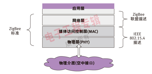
Figure 1: ZigBee based on 802.15.4 provides network layer and application layer specifications. 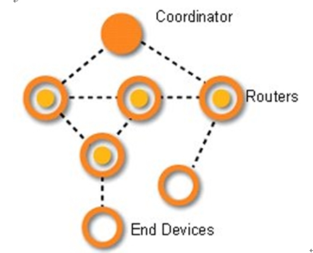
Figure 2: ZigBee mesh topology. 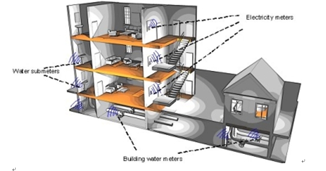
Figure 3: Application of wireless meter reading in residential buildings. 