Design of hardware and driver for vehicle network system
1 Introduction
With the rapid development of electronic technology and the widespread application in automobiles today, the degree of electronicization of automobiles is getting higher and higher. The numerous electronic controls and increased communication complexity in the automotive electronic system will inevitably lead to huge and complicated wiring of the entire vehicle, a shortage of installation space, reduced operational reliability, and increased difficulty in troubleshooting. In addition, in order to improve the signal utilization rate, data and information communication and resource sharing are required. The traditional point-to-point communication method of the electrical system can no longer meet this demand. For the above problems, based on the existing mature computer network and modern control technology, automotive network technology came into being. The various electronic devices and devices on the car are connected into a network through the bus to achieve information sharing between the devices, which not only reduces the wiring harness, but also can better control and coordinate the various systems of the car to achieve the best car performance.
2 System hardware design
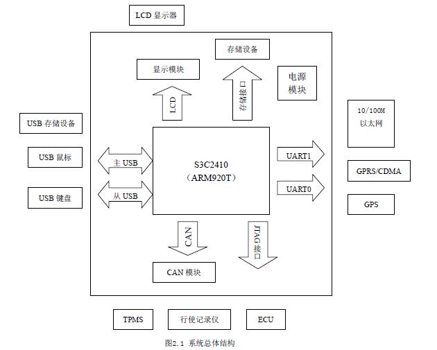
The vehicle-mounted network designed by this hardware system has data processing, data storage, data communication, parameter setting, display and other functions, which can well collect data such as vehicle speed, vehicle interior temperature, engine operating status, water temperature and fuel quantity collected by the sensor Transmission, processing, storage, and display through the display screen, so that the driver can keep abreast of the overall running status of the car body. The system is mainly divided into processor module, USB interface module, storage module, UART asynchronous serial port module, CAN module, 10 / 100M Ethernet interface module, display module and power supply according to function. The overall structure of the system is shown in Figure 2.1.
2.1 Processor module
The system uses a 32-bit RISC microprocessor S3C2410 developed by Samsung, which contains an ARM920T core. The chip integrates 16KB instruction cache, 16KB data cache, MMU, external memory controller, NANDFlash controller, 1 LCD control Controller, SDRAM controller, 3 channels, two independent UARTs, 4 channels of DMA, 8 channels of 10-bit ADC, touch screen interface, IIC bus interface, 1 USB host interface, 1 USB device interface, 117-bit universal I / O port and 24-bit external interrupt source. S3C2410x supports booting from NAND Flash. The system uses a combination of NAND Flash and SDRAM to obtain a very high cost performance.
2.2USB interface module
The S3C2410's USB supports the USB 1.1 version, which is suspended and awakened. The USB device controller can provide a high-performance and complete rate function control solution with a DMA interface, allowing batch transfer, interrupt transfer, and control transfer. S3C2410 is very convenient to expand USB. It can be connected according to the USB1.1 standard protocol. It can support low-speed and high-speed transmission of USB at the same time.
2.3UART serial port module
UART refers to asynchronous serial port. There are two UART0 and UART1 in the ARM9 microcontroller. UART0 only provides TXD and RXD signal pins, UART1 adds a modulation interceptor MODEM interface, the other two are completely the same.
2.4 CAN module
This system adopts the independent CAN controller MCP2510 produced by Philips, which is suitable for automobile environment and general industrial system environment. MCP2510 supports CAN2.0B, and has some new features, is widely used, is a typical independent CAN controller. The SJA1000 has two modes of operation, the basic CAN mode and the Peli CAN mode with many extended functions.
2.5 display module
Because the chip used in this system has integrated the LCD controller, so long as you choose the appropriate LCD display. The system selects SHARP's LQ080V3DG01 display screen. LQ080V3DG01 is a TFT-LCD display module, which is composed of color TFT-LCD template, drive circuit, control circuit, power supply circuit and backlight unit. The display resolution is RGB640 × 480, with two power supply modes of 3.3V and 5V.
3 driver design
The software of the vehicle-mounted network system is composed of three parts: real-time operating system, hardware driver, and applications running on the operating system, 10 / 100M Ethernet USB storage device, USB mouse, USB keyboard, GPRS / CDMA, GPS. The real-time operating system uses the Linux operating system with open source code. The hardware drivers are mainly USB device drivers, CAN controller drivers, serial port drivers and LCD controller drivers.
3.1 Design of USB device driver
Linux's USB kernel subsystem provides several core data structures directly related to device driver development, which are defined in the kernel source code
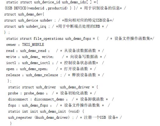
The above is the framework of a typical USB device driver in Linux, which usually includes device initialization, device unloading, device opening, device release, and reading, writing, and controlling the device. It is a relatively fixed format.
3.2 Design of CAN controller driver
There are specific rules and some necessary modules for writing drivers under Linux. The init_module module is used to load devices in the driver and is called when the system is initialized. Here arm9200_mcp2510_init () is used as the entry function of the CAN bus driver. He will mainly complete the initialization of the MCP2510, call the register_chrdev () function to register the character device driver with the system, and use the request_irq () function as the interrupt handler of the CAN bus. According to the requirements for transferring CAN data, the following data structure is designed to store a frame of data and manage the receive buffer:
Typedef struct {unsigned int id; / * Identifier of nodes in CAN network * /
unsigned char data [8]; / * The data to be transmitted, the maximum is 8 bytes * /
unsigned char dlc; / * length of data sent * /
int IsExt; / * Determine whether the message is an extended frame * /
}
candata; Typedef struct {Candata MCP2510_Candata [128]; / * Define a receive buffer * /
int nCanRevpos; / * pointer to the location where data is stored in the buffer * /
int nCanReadpos; / * Position pointer of data read out * /
int loopbackmode;
wait_queue_head_t wq;
spinlock_t lock;
}
MCP2510_DEV;
The data structure file_operaTIons is an important data structure in the driver. The kernel accesses the driver through this structure. The application program reads and writes data and controls the work of the character device by calling the corresponding program in the driver to the _read (), _write (), _ioctl () functions.
3.3 Design of serial port driver
The serial port driver uses the query method, which mainly includes the serial port initialization function, data receiving function and data sending function. The serial port initialization function USIinit () is mainly used to set the parameters of the USART work. The user application can perform various processing on the received function by calling the data receiving function RevUSData (). USART data receiving and sending are both an active process, so the design of this function is relatively simple. The data sending function SendUSData () is similar to the data receiving function and can be called by the user program.
3.4 Design of LCD controller driver
The first thing in driving the LCD design process is to configure the LCD controller, and the most important thing when configuring the LCD controller is to specify the frame buffer (FrameBuffer). The device file corresponding to the frame buffer device is / dev / fb *, and the data structure is as follows:
StaTIc struct file_operaTIons
fb_fops = {ower: THIS_MODULE,
read: fb_read,
write: fb_write,
ioctl: fb_ioctl,
mmap: fb_mmap,
open: fb_open,
}
The functions in it operate on specific hardware, set registers, and map display buffers. The initialization function first initializes the LCD controller. In Linux, you can use the kmalloc () function to dynamically allocate continuous LCD display buffers. The next step is to initialize an fb_info structure, add member variables, call register_framebuffer (& fb_info), and register fb_info into the kernel. Member functions of structure fb_info:
struct fb_ops {
int (* fb_get_fix) (struct fb_fix_screeninfo * fix, int con, struct fb_info * info);
int (* fb_get_var) (struct fb_var_screeninfo * var, int con, struct fb_info * info);
int (* fb_set_var) (struct fb_var_screeninfo * var, int con, struct fb_info * info);
}
4 Conclusion
This article details the design of the underlying hardware and driver of the embedded vehicle network system and successfully completes the debugging of the hardware and software. The author's innovation: This network system greatly reduces the number of electronic control devices, saves the valuable space resources of the car occupied by the thick wire harness, and realizes the data sharing, communication and processing between the electronic instruments inside the car, thereby improving the safety of the car. performance.
Our company is specialized in supplying AC Bracket, AC Support, Air Conditioner Bracket, Air Conditioner Support Bracket. We could supply different type of brackets with different sizes. It could suitable for 0.75HP, 1. HP, 1.5HP, 2HP, 3HP, 4HP etc. Tell me the measurement, material and thickness. Our products are widely used in electronic appliances, lighting, switch, sanitary, sanitary ware, jewelry, watches, toys, furniture, gifts, handbags, umbrellas, doors and windows. Stainless Steel: SS201, SS301, SS303, SS304, SS316, SS416. Steel: Q235B, Q195, Q345.Brass: C36000, Bronze: C51000, C52100, C54400. Iron: 1213, 12L14, 1215. Aluminum: Al6061, Al6063.RUBBER: EPDM, NR, SBR, HNBR, NBR, CR, FPM...
Air Conditioner Bracket
Air Conditioner Bracket,Air Conditioner Support Bracket,Air Conditioner Support,Window Air Conditioner Bracket
ZHEJIANG ICE LOONG ENVIRONMENTAL SCI-TECH CO.,LTD. , https://www.ice-loong.com