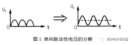
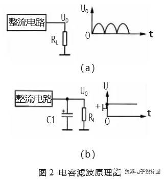
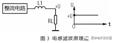
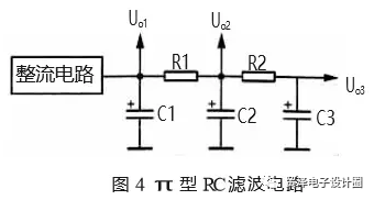
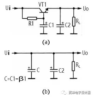
Introduction The output voltage from a rectifier circuit is typically a one-way pulsating DC voltage, which is not suitable for direct use in electronic circuits due to its fluctuating nature. To make it usable, the AC components must be removed, converting the voltage into a more stable DC power source. This process is achieved using filter circuits that utilize components with specific impedance characteristics to AC signals, such as capacitors and inductors. This paper explores different types of filter circuits and their working principles. 1. Types of Filter Circuits There are several common types of filter circuits used in power supplies. These include the basic capacitor filter, the π-type RC filter, the π-type LC filter, and the electronic filter. Each type has its own advantages and applications depending on the required filtering performance and design constraints. 2. Principles of Filtering 2.1 Characteristics of Unidirectional Pulsating DC Voltage A unidirectional pulsating DC voltage, as shown in Figure 1(a), maintains a consistent direction but varies in amplitude over time. This periodic variation makes it unsuitable for most electronic devices. According to waveform decomposition principles, this voltage can be broken down into a DC component and multiple AC components at different frequencies, as illustrated in Figure 1(b). The solid line represents the DC component, while the dotted line shows the AC ripple superimposed on it. 2.2 Capacitor Filtering Principle Capacitors are widely used in filter circuits due to their ability to pass AC while blocking DC. In a basic capacitor filter, as shown in Figure 2(a), the rectified voltage is applied to the load through a capacitor. When the voltage rises, the capacitor charges; when it drops, the capacitor discharges, smoothing out the pulsations. This creates a more stable DC output. As depicted in Figure 2(b), the capacitor acts as an open circuit to DC, allowing only the DC component to reach the load. Meanwhile, the AC component flows through the capacitor to ground, effectively reducing the ripple. The larger the capacitance, the better the filtering effect, as it reduces the AC reactance and minimizes the remaining ripple on the load. 2.3 Inductor Filtering Principle Inductors, on the other hand, allow DC to pass easily while resisting AC. In an inductor filter (Figure 3), the inductor is placed in series with the load. The DC voltage passes through the inductor with minimal resistance, while the AC component is impeded by the inductive reactance, preventing it from reaching the load. This results in a smoother DC output. However, increasing the inductance also increases the DC resistance, which may cause a slight voltage drop. Therefore, a balance between filtering effectiveness and DC resistance must be maintained. 3. π-Type RC Filter Circuit The π-type RC filter circuit, as shown in Figure 4, consists of two capacitors and a resistor arranged in a π shape. This configuration provides improved filtering compared to a single capacitor. The first capacitor (C1) filters out most of the AC component, while the second capacitor (C2) further smooths the signal. The resistor (R1) helps to create a voltage divider that enhances the filtering effect. The filtering mechanism involves both capacitive and resistive elements. For AC signals, the capacitor offers low reactance, allowing the AC component to bypass the load. For DC, the capacitor blocks the signal, ensuring that only the desired DC voltage reaches the output. Adjusting the values of R1 and C2 can optimize the filtering performance. 4. π-Type LC Filter Circuit The π-type LC filter circuit replaces the resistor in the RC filter with an inductor. This allows the circuit to maintain a higher DC output voltage while still effectively filtering out AC components. The inductor offers low resistance to DC and high resistance to AC, making it ideal for filtering applications where voltage stability is crucial. In this configuration, the capacitor (C1) initially filters out most of the AC, while the inductor (L1) and capacitor (C2) work together to further reduce any remaining ripple. This combination results in a cleaner DC output. 5. Electronic Filter Circuits Electronic filters use active components like transistors to enhance filtering performance. In a typical electronic filter (Figure 6), a transistor (VT1) acts as a filter tube, with a base capacitor (C1) and a bias resistor (R1) forming the filtering network. The output is further filtered by another capacitor (C2). The principle behind this circuit is that the transistor amplifies the effective capacitance of C1, improving the filtering effect. Additionally, the base current is much smaller than the emitter current, allowing for a larger resistance without significant voltage loss. This makes the electronic filter highly efficient and suitable for precision applications. An alternative version includes a Zener diode (VD1) to provide voltage regulation. This ensures that the output remains stable, even under varying load conditions. The Zener diode stabilizes the base voltage, resulting in a more consistent DC output from the emitter. 6. Summary of Power Supply Filter Circuits In summary, understanding the working principles of various filter circuits is essential for designing effective power supply systems. Key points to consider include: - Capacitors act as AC short circuits and DC open circuits, allowing them to filter out ripples effectively. - Inductors offer low resistance to DC and high resistance to AC, making them useful for filtering applications. - Electronic filters use transistors to amplify the effective capacitance, enhancing filtering performance. - Adding a Zener diode to an electronic filter can improve voltage regulation and stability. By carefully selecting and combining these components, engineers can design power supplies that provide clean, stable DC voltages for a wide range of electronic applications. Digital Clamp Meter ,Digital Clamp Multimeter,Clamp Meter,Ac Clamp Meters YINTE TOOLS (NINGBO) CO., LTD , https://www.yinte-tools.com