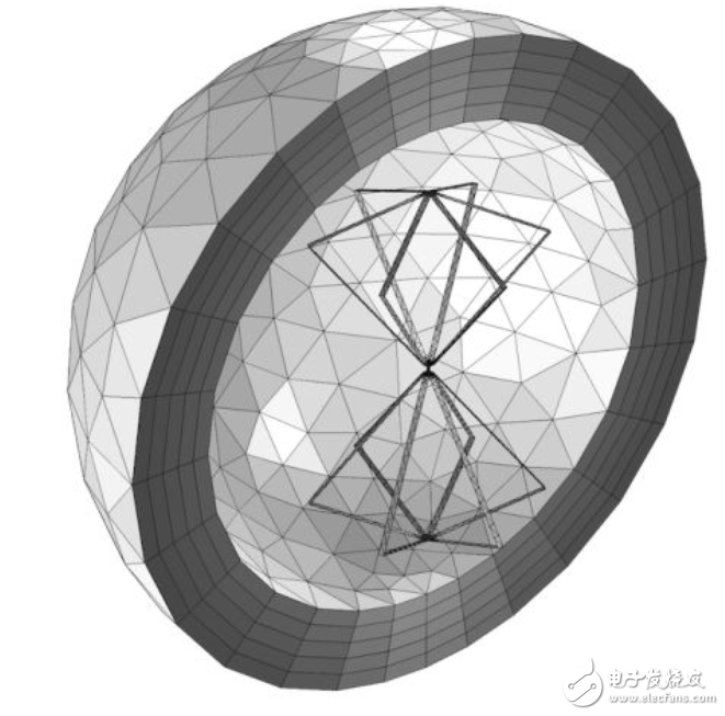
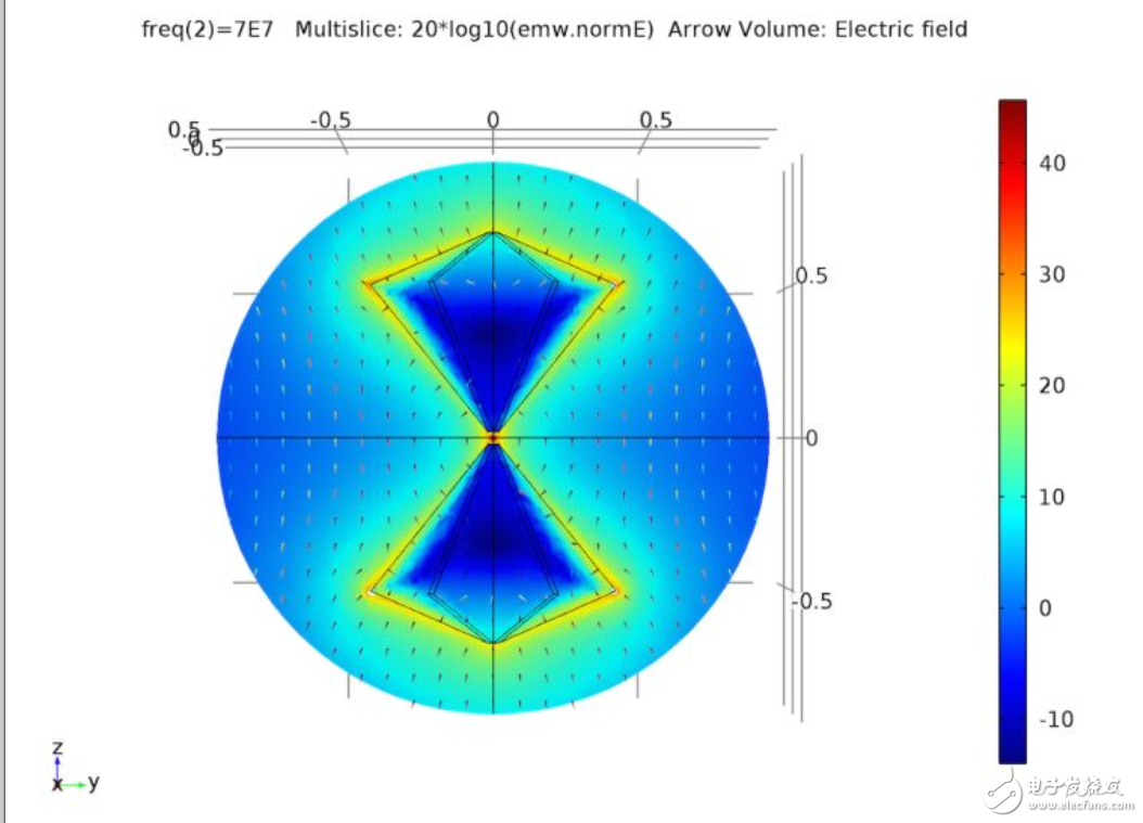
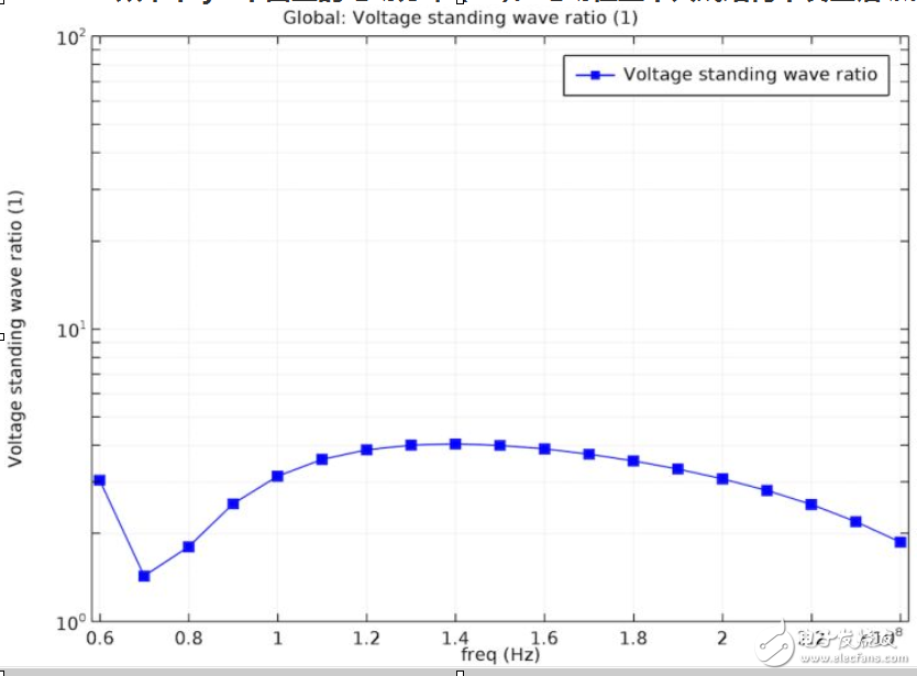
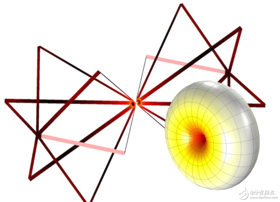
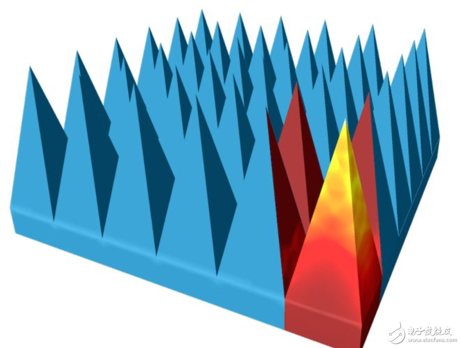
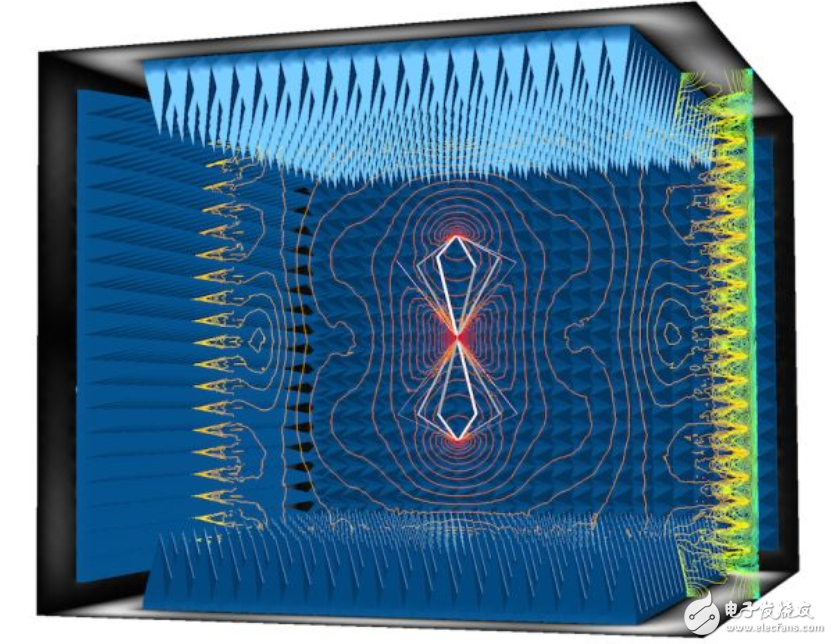
How to simulate the absorbing chamber in electromagnetic simulation, by adjusting the operating frequency of the absorbing device, it can be combined with the double-cone antenna tuned to the UHF band. In the simulation, the frame of the double-cone antenna is used as the boundary simulation, and the three-dimensional far-field mode at 70 MHz is similar to the mode of the typical half-wave dipole antenna. Through electromagnetic simulation, we finally hope to improve equipment efficiency and productivity by precisely simulating the effects we observe in the real world. In this process, you first need to understand the real situation that you are trying to describe and simulate, and the details that should be added. We will explore real electromagnetic waves in the measurement environment in our blog. When characterizing an electronic device used to emit electromagnetic waves, we need to ensure that the radiated wave does not return to the device under test (DUT). When the reflected wave is superimposed on the original wave, it will cause phase distortion, so there is no infinite space around any object is the most ideal choice. In this kind of environment, there is no influence caused by reflection such as multipath fading. The market is closest to the Earth scene, but it is still significantly affected by the ground. If we understand the exact spatial configuration between the transmitter and the receiver, and can be sure that only the ground will distort the electromagnetic waves, the excess signal path can be removed through the time window features of the network analyzer. But because every test needs to drag this heavy machine to the market, it is not the best choice. As an alternative, it would be very convenient if you could implement an effective infinite space in the lab, that is, the entire room. The walls of the room will absorb the incident waves and will not interfere with the DUT. Antenna measurement in the all-room. In the "Improving RF Full Room with Periodic Structure" blog, we demonstrated how to design a microwave absorber with COMSOL MulTIphysics and RF modules. The pyramidal periodic loss structure gradually attenuates the incident wave and produces almost no reflection, thus making the whole room a non-interfering environment. So, can we use these absorbers to simulate an antenna in a silent room? of course can! A conventional microwave absorber used in a completely silent room. We magnified the geometry of the original pyramidal object by adjusting the operating frequency of the absorber to allow it to be used in conjunction with a double-cone antenna tuned to the UHF band. The size of the pyramidal object is proportional to the wavelength to be measured. The development steps of the all-room model are similar to the development of a real room. We will first create an empty room of 3.9 * 3.9 * 3.2 m. The outer wall is covered by a perfect electrical conductor to simulate a conductive layer of sufficient thickness to block all outdoor incident signals. A microwave absorber is installed on all six walls. We have a biconical antenna tutorial model for EMI/EMC testing in the center of the room. The results show that the performance of the antenna is similar to the results in the App library example. The figure below shows a better plot of the electric field size. Since the geometry and size of the room are complex, we need 16 GB of memory to run the simulation. However, the approach we will describe next will simplify the process. Several methods of simulating open boundary domains have been described in detail before, with particular reference to perfect matching layers and scattering boundary conditions. We can create the ideal all-room in the simulation environment with the perfect matching layer (PML). In the simulation, the frame of the double-cone antenna is simulated as a boundary, and the surrounding air domain and the perfect matching layer are also required. Only half of the PML layers are shown in the figure. The operating frequency in this example is the conventional VHF band (60 MHz – 240 MHz). To simplify the modeling steps and reduce the computational resources required, we assume that the frame structure of the antenna is an extremely thin geometric plane. Since the thickness in a given frequency range is greater than the skin depth, the structure can be modeled as a perfect electrical conductor. For the gap placed in the center of the two hexagonal frame structures, designate it as a lumped port with a reference impedance of 50 Ω. The antenna is surrounded by a spherical air domain, and the outermost layer of the air domain is configured as a PML layer, which is responsible for absorbing all outward radiation of the antenna and is used as a silent room in the simulation. Electric field distribution (dB) in the yz plane at 70 MHz. The electric field resonates throughout the antenna structure. The voltage standing wave ratio (VSWR) plot (the logarithmic scale is used for the y-axis); the picture shows that the mean of VSWR is approximately 3:1. The figure above shows the distribution of the electric field (dB) and plots the directionality of the electric field at 70 MHz using an arrow diagram. When the frequency is in the lower range, the electric field is confined throughout the structure. As the frequency increases, the reaction zone will gradually decrease. Therefore, the portion of the antenna structure that responds to electromagnetic waves shrinks along the center of the lumped port. The calculated VSWR average is approximately 3:1 and the performance is close to the EMI/EMC measurement of the double-cone antenna commercial product. The 3D far field mode at 70 MHz is similar to the mode of a typical half-wave dipole antenna. The three-dimensional far-field radiation pattern shows the same omnidirectional features as the H-plane. Based on the modeling configuration recommendations, we now need less than 2 GB of memory to calculate the far-field radiation pattern and the VSWR value of a double-cone antenna with a lightweight hexagonal frame. Therefore, we can complete the model setup more easily and quickly than the complete full room simulation. SSMB Cable Mount Connectors,SSMB Bulkhead Mount Connectors,SSMB Flange Mount Connectors,SSMB Pcb Mount Connectors Xi'an KNT Scien-tech Co., Ltd , https://www.honorconnector.com
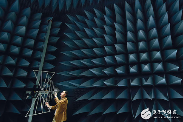
 Simulation of a double cone antenna in a silent room.