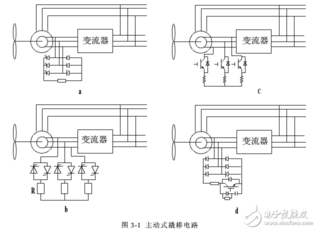
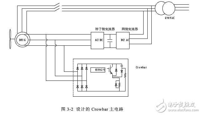
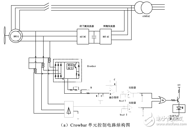
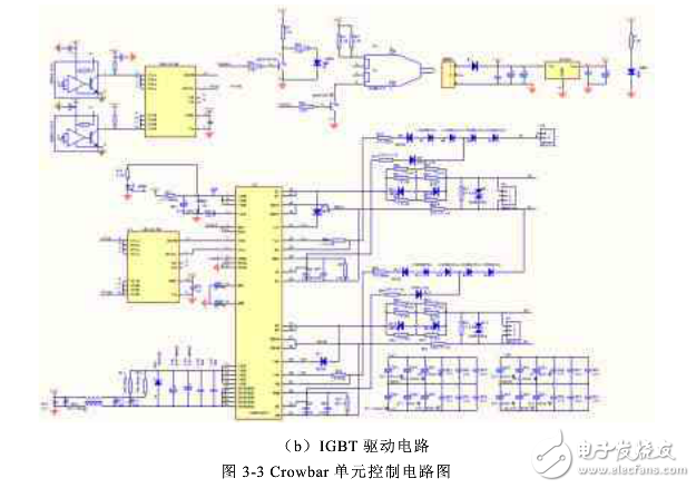
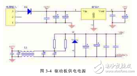
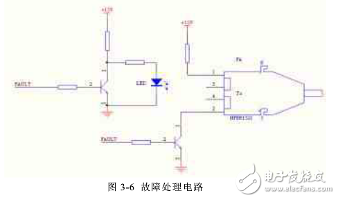
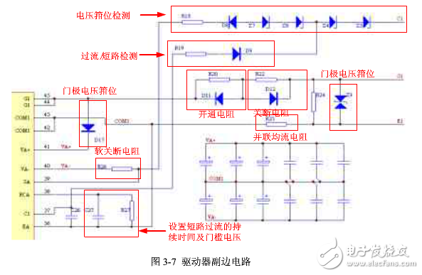
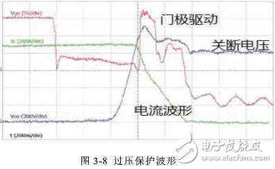
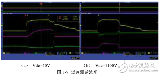
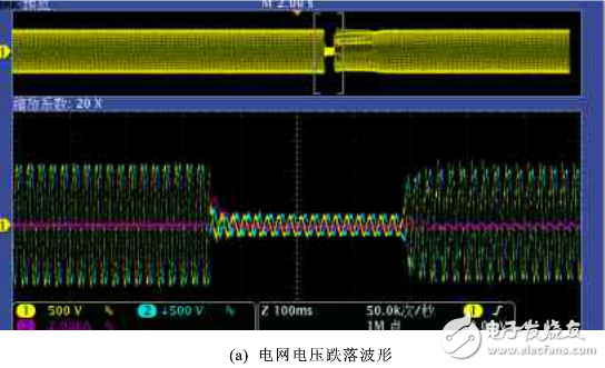
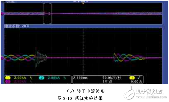
The doubly-fed wind turbine is currently the mainstream model in the wind power field. More than 70% of the installed wind turbines are doubly-fed systems. For the converter, the main advantage of the doubly-fed system is that only part of the power flows through the converter, and the active and reactive power can be adjusted separately. However, due to the small capacity of the converter, it is very sensitive to grid faults and requires reliable protection against damage to the power devices in the converter. As mentioned above, during the transition of the grid voltage drop, attenuated DC components appear in the stator flux of the doubly-fed machine, and negative sequence components also occur when an asymmetric drop fault occurs. The DC component and the negative sequence component form a large slip for a doubly-fed rotor that operates at a higher rotational speed, thereby inducing a larger rotor voltage and rotor current in the doubly-fed rotor circuit. The higher amount of transient current and voltage in the rotor circuit poses a threat to the safe operation of fragile semiconductor converter devices in rotor converters. When wind power has not yet formed a scale, wind turbines mainly design Crowbar circuits from the perspective of self-protection. The Crowbar circuits used in this period are mostly passive, so-called "thyristor" Crowbar circuits. When the voltage drop occurs in the grid, the most common method is to short-circuit the doubly-fed motor directly through the thyristor. At this time, the doubly-fed motor operates as a squirrel-cage asynchronous motor; when the grid fault is eliminated, the doubly-fed generator is off the stator side. The net, the thyristor is turned off, and the doubly-fed motor is re-connected to the grid. When a passive Crowbar is used, the doubly-fed generator always operates in the state of a squirrel cage asynchronous generator in the event of a grid failure, requiring a large amount of reactive power to be absorbed from the grid. Since the German E.ON company first proposed grid-connected wind power generation in 2003, the traditional wind turbine based on the passive Crowbar circuit has been unable to meet the new requirements of electric power operators for wind power generation. In order to meet the electric power operator's further requirements for wind power generation, it is necessary to disconnect the crowbar circuit at an appropriate time to ensure that the rotor converter restarts when the fan is not off-grid, so a new type can be found. The "active Crowbar" protection circuit of the rotor circuit is cut off at any time. In the active Crowbar protection circuit, a shutdown device such as an IGBT is often provided. Based on the analysis of the operating characteristics of the doubly-fed wind turbine during the voltage drop, the main circuit of Crowbar and its control circuit are designed with 1.5MW doubly-fed as an example, and the experimental verification is carried out on the 2MW experimental platform. The common active Crowbar circuit structure is shown in Figure 3-1. The circuit shown in Figure 3-1(a) consists of a series of control devices such as thyristors and diodes connected in series. The circuit shown in Figure 3-1(b) consists of two anti-parallel thyristors. The above two methods are used to control the turn-on of the thyristor into the Crowbar circuit, and the thyristor is cut off by zero-crossing. Figure 3-1(c) and Figure 3-1(d) use IGBT as the switching device. Figure 3-1(c) uses one IGBT to control the bypass resistor switching for each bridge arm. More, the cost is higher, Figure 3-1 (d) first through the diode rectification, and then through the IGBT switching bypass resistor, only use one IGBT, and the diode's overcurrent capability is extremely strong, the capacity can be selected relatively small . From an engineering perspective, the cost is relatively low. This paper selects the circuit structure of Figure 3-1 (d) as the Crowbar main circuit. The choice of IGBT depends on the factors that need to be considered, including the size of the shunt resistor and the operating time of the Crowbar circuit. Taking the 1.5MW doubly-fed system as an example, considering the worst case, when the grid drops to 0 and the fan system is fully loaded, the 1.5MW energy needs to be consumed by the bypass resistor in the Crowbar, so the resistance can be obtained. The size is R=690*690*1.732/1.5MW=0.549Ω, considering the temperature drift of the resistor at 10% at high temperature, the actual selected resistance is 0.49Ω. According to the system control mode, the Crowbar circuit is generally input at the moment when the power grid falls and recovers. The impact of the voltage drop is the largest. When the voltage is restored, the Crowbar can be determined according to the system requirements and the control mode adopted. According to the design of the system LVRT working mode, the Crowbar's working time is generally 60-80ms when the grid voltage drops. The actual working time is determined by the rotor side current and voltage. During this time, the IGBT remains on. The maximum current of the IGBT during operation can be obtained from the size of the above resistor, and the heat capacity of the IGBT can be determined by the operating time of the Crowbar circuit. Combined with the operating characteristics of the IGBT, the rated current of the IGBT can be selected. The rated voltage rating of the IGBT is the same as that of the main circuit of the converter, which is 1700V. The actual selected IGBT is 1700V, 2400A. Since the bypass resistor itself has a certain self-inductance, in order to provide a freewheeling circuit after the IGBT is turned off, a diode with a small power is required across the bypass resistor. The specific parameters of the diode are determined by the ESL of the shunt resistor. At the same time, in order to reduce the parasitic inductance of the IGBT switching circuit as much as possible to reduce the IGBT turn-off voltage spike, the freewheeling diodes of the IGBT and the rectifier diode and the shunt resistor need to be placed nearby. At the same time, the IGBT is designed to absorb the circuit The detailed Crowbar main circuit diagram is shown in Figure 3-2. It can be seen from the previous analysis that when the voltage drops, the doubly-fed system exhibits overcurrent and overvoltage on the rotor side, so the rotor current and voltage are taken as the basic conditions for Crowbar operation. By detecting the rotor voltage and comparing it with the reference value, the conduction of the IGBT in the Crowbar circuit is controlled, and the AC current of the Crowbar circuit is judged, and after comparison with the reference value, the turn-off of the IGBT in the Crowbar circuit is controlled. The detailed control circuit is shown in Figure 3-3. Figure 3-3 (a) shows the Crowbar unit control circuit structure, which includes the Crowbar unit main circuit, the rotor side voltage detection circuit, and the Crowbar unit three-phase AC current detecting unit. Figure 3-3(b) shows the drive circuit of the IGBT. It contains IGBT driver and IGBT protection circuit. The basic working principle is as follows: The condition that Crowbar is put into, that is, the condition that the IGBT is turned on is: an overvoltage is detected on the rotor side. Using the three-phase diode in the main circuit of the Crowbar unit, the three-phase AC voltage on the rotor voltage side is converted into a DC voltage. After proper filtering, the DC voltage is detected and compared with the reference voltage Vref1. Under normal circumstances, the comparator output is low. Level, when it is detected that the DC voltage exceeds a certain value, the comparator operates and outputs a high level, and the IGBT conductor is triggered by the driving circuit of the IGBT. In order to improve the anti-interference ability of the control circuit and prevent false triggering, a differential circuit is used to detect the DC voltage. After the IGBT in the Crowbar is turned on, the current on the rotor side is transferred to the Crowbar unit. All of the voltage drops fall on the shunt resistor. The reduction of the DC voltage will cause it to lose control of the Crowbar. At this time, the current on the rotor side may still exceed the tolerance of the machine-side converter. At this time, it is necessary to judge whether the Crowbar unit's three-phase AC current is used as Crowbar. Working conditions. In this paper, a current transformer is used to detect the three-phase AC current and compare it with the reference value Vref2. When the current is higher than a certain value, the IGBT continues to conduct. When the current is lower than a certain value, the output of the comparator becomes a low level, the IGBT is turned off, and the Crowbar unit is cut off. Figure 3-3 (b) is the driving circuit of IGBT. This paper selects the driver chip 2SD300C17 developed by concept company for high-power IGBT as the core driver, and designs the peripheral circuit, including the input signal processing and power supply filtering of the primary side of the driver. Overvoltage protection and overcurrent protection circuit on the secondary side. See Appendix 1 of this chapter for a detailed description of the 2SD300C17. (1) Driver primary circuit design 1) Driver board power supply design A total of 15V and 5V power supplies are required inside the driver board. 15V supplies power to the driver core and 5V supplies power to the fiber head. The 15V power supply is provided by an external 24/15V power supply module, and the 5V is obtained by a three-terminal regulator H7805 through 15V conversion to supply power to the fiber head. As shown in Figure 3-4, it contains the filter circuit and the protection circuit. 2) Optical fiber signal receiving circuit In order to improve the anti-interference ability of the system, the driving signal is transmitted by optical fiber. The fiber input signal is generated by the logic signal generated in Figure 3-3(a) through the fiber converter and transmitted to the driver board through the fiber. The optical signal receiving circuit is designed on the driver board, as shown in Figure 3-5. 3) Fault signal processing The SOX pin of 2SD300C17 is the fault signal output end. When the fault is normal, the pin is high level. When the fault is blocked or the power supply is under voltage, the output is high impedance and the output is low. Figure 3-6 shows the fault signal processing circuit of the drive board. On the one hand, the fault is indicated by the LED, and on the other hand, the fault signal is returned to the main control board of the cabinet through the optical fiber. (2) Driver secondary circuit design The secondary circuit of the driver is shown in Figure 3-7. It includes a drive signal processing circuit and an overcurrent and overvoltage protection circuit. 1) Overcurrent and short circuit protection circuit 2SD300C17 determines whether there is an overcurrent or short circuit condition by detecting the voltage of Vce after the IGBT is turned on. After the tube is turned on, the chip starts detecting the voltage of vce after a certain response time (this time is determined by R19 and C26 in Figure 3-7). If this voltage is greater than the dynamic reference voltage Vth determined by Rth and Cth, the chip considers a short circuit or overcurrent fault to occur, turns off the PWM output, and outputs a fault FA signal. 2) Active clamp and soft shutdown circuit When the chip detects a short circuit or overcurrent and needs to turn off the switch, a large di/dt will generate a large voltage spike across the switch, which may damage the switch. In order to prevent this from happening, the 2SD300C17 chip has a soft-shutdown function, as shown in Figure 3-7. R26 is a soft-shutdown resistor. Its function is to turn off the switch when detecting a short circuit or overcurrent. The output capacitor is reversely charged, and the input capacitance Cies of the IGBT and the Miller capacitor Cres are slowly discharged, slowing down the turn-off speed of the drive, thereby reducing the voltage spike of the switch. Soft turn-off does not prevent overvoltage under any circumstances. For example, when the turn-on time of the switch is shorter than the detection response time when the short circuit occurs, the soft turn-off does not work. At this time, the chip is protected by a voltage clamping circuit to ensure that the switching tube does not turn off when the voltage spikes. In the above figure, the voltage spike limit is determined by setting the appropriate Z4, Z5, Z7, Z8. When vce is greater than this value, current flows from the C1 terminal to the gate through R18. When the current is large enough, it will appear. The second opening phenomenon, the ultimate goal is to reduce the turn-off spike. (1) Overvoltage protection test Figure 3-8 shows the action waveform of the overvoltage protection of the drive circuit. It can be seen from the figure that when a higher voltage occurs during the turn-off of the IGBT, the active clamp circuit operates and the gate drive signal changes from low to low again. A high level turns the IGBT on to reduce excessive turn-off voltage spikes. (2) Short circuit test Take Rth=12k, Cth=560pF, and the short-circuit response time is about 6us. Figure 3-9 shows the short-circuit waveforms at Vdc=50V and Vdc=1100V (CH1 is the drive waveform, CH3 is the short-circuit current waveform, and CH4 is the Vce waveform). It can be seen from the figure that the switch is turned off after the short circuit occurs for 5.72us, and the soft turn-off function makes the driving voltage drop slowly, and controls the voltage spike at the time of turn-off. In order to verify the analysis of the above problems, the experimental verification was carried out on a 1.5MW doubly-fed test bench. The experimental results are as follows: The experimental results show that the designed Crowbar reacts quickly during the voltage drop and works stably. It achieves better protection function for the converter and realizes the low voltage ride-through function with the converter system. In this chapter, the working characteristics of the doubly-fed wind power generation system during voltage drop are analyzed in detail. On this basis, the main circuit of Crowbar unit and its driving circuit are designed. Taking 1.5MW double feed as an example, the hardware circuit is designed in detail for the system, and the test is verified. The test results show that during the low voltage ride-through period, the designed Crowbar circuit operates in time, which not only achieves a good protection function for the converter, but also achieves a low voltage ride-through function with the converter system, which satisfies the current state. Grid regulations on the access of wind power to the grid. Molded Waterproofing Cable Assemblies We specialize in waterproofing products overmolding. We can custom build, custom mold, and over-mold your cable designs.
We specialize in molded cable manufacturing for the widest diversity of
cable and connector types, across the whole spectrum of industries. Rich expeirence in developing and proposing solution Special for IP67, IP68 waterproofing products. Molded waterproofing cable assemblies, waterproof wire harness, waterproofing cables overmolding ETOP WIREHARNESS LIMITED , https://www.oemmoldedcables.com