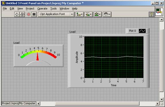
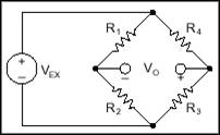
Based on PC data acquisition, measurement is performed through a combination of modular hardware, application software, and a computer. Although data acquisition systems have different definitions based on different application requirements, the purpose of each system to collect, analyze, and display information is the same. The data acquisition system integrates signals, sensors, actuators, signal conditioning, data acquisition equipment, and application software. Load Cell and Pressure Sensor - Overview of Operating Principles The load cell is a sensor that converts mechanical forces into electrical signals. The working principle of different types of load cells is not the same, but strain gauges are the most commonly used. As the name implies, the strain gauge element senses the deformation of the structure through strain gage arrays and converts the strain into electrical signals. The same applies to pressure sensors. The strain gage is installed on the pressure beam and measures the deformation of the pressure beam. The strain is proportional to the pressure. The following sections describe the working principle of the strain gauge load cell and how it is measured. Of course, the principle applies to strain gauge pressure sensors. Before understanding the working principle of the load cell, first understand the basic theory behind the principle. As mentioned earlier, the strain gauge obtains the applied pressure (load) by measuring the deformation (strain). The strain is defined by the differential variable of the length. More precisely, the strain is the change in length dL divided by the original length L, and the change in this quantity is proportional to the additional load. Figure 1 explains this concept. By measuring the strain and understanding the physical properties of the stressed structure, we can accurately calculate the pressure. Figure 1. Strain There are several ways to measure stress. The most common method is to use a strain gauge. Its resistance change is proportional to the applied stress. The most commonly used strain gauge is a gluing metal strain gauge, as shown in Figure 2. Figure 2. Bonded Metal Strain Gauge As the stress changes, the resistance changes, but of course the change is very small. We need to amplify this change by the circuit. The most common circuit structure in load cells is called the Wheatstone bridge. The conventional Wheatstone bridge, as shown in Figure 3, consists of four bridge arms that operate through the excitation voltage VEX. Figure 3. Wheatstone Bridge The output voltage VO of the bridge is expressed by the following formula: Load cells typically use four strain gages in a Wheatstone bridge so that each arm of the circuit functions. This structure is called a full bridge. The use of a full-bridge structure greatly increases the circuit's sensitivity to stress changes and makes measurements more accurate. Although there are more in-depth theories about the Wheatstone bridge, you don't need to know because the load cell is usually a "black box" with two-wire excitation signals (0 V and Vex) and two-wire output signals ( AI+ and AI-). The manufacturer of the load cell makes a calibration curve for each device, indicating the relationship between the output voltage and the specific load. How to Implement Load Cell/Pressure Sensor Measurements <br> The following section describes the data acquisition and signal conditioning equipment required for effective load cell/pressure sensor measurements. The basic measurement needs include: excitation, signal amplification, balanced bridges. Bridge excitation The signal conditioning circuit of the load cell usually provides a constant voltage source to power the bridge. Although standard voltage levels are not specified on an industrial scale, the excitation voltage is generally between 3 and 10 volts. Higher excitation voltages can produce proportionally higher output voltages, but at the same time they can cause higher errors due to self-heating. It is very important that the excitation voltage must be very accurate and stable. Signal amplification The output of load cells and bridges is relatively small. In practice, most load cells and load-based sensor outputs are less than 10 mV/V (output voltage is 10 mV per volt of excitation voltage). 10 volt excitation voltage, the output signal is 100 mV. Therefore, the signal conditioning circuit of the load cell typically includes an amplifying portion to enhance the signal to increase the resolution of the measurement and improve the signal-to-noise ratio. Bridge balance, zero adjustment It is difficult to ensure that the output is accurate to zero when the installed bridge is in the state of zero stress. The slight difference between the bridge arm resistance and the wire resistance will cause the bridge to output a non-zero initial offset voltage. The following method can solve the problem of the initial offset voltage of the system. Software Compensation - The first method of compensating offset voltage is to compensate in software. Perform an initial test before use. We call it auto-zero. This method is simple, fast, and does not require manual adjustment. However, the disadvantage is that the offset output of the bridge is not eliminated. In the case of a large offset, the gain of the output voltage amplifier is limited, which in turn limits the dynamic range of the measurement. The required equipment includes: - cDAQ-9172 8-Slot Hi-Speed ​​USB Chassis for NI CompactDAQ - NI 9237 4-Channel, ±25 mV/V, 24-Bit Synchronous Bridge Module - Full bridge load cell The NI 9237 has four RJ-50 sockets that can be connected to four half-bridges or full-bridges. The NI 9237 also includes a 4-pin connector that can be used to connect an external excitation voltage source. Figure 4 shows the location of the connectors on the bottom of the NI 9237 module. It also shows how the full-bridge structure is connected. Figure 4. Connection method of full bridge structure Measurement Visualization: NI LabVIEW In the example in Figure 5, the stress measurement data can be displayed in the instruction chart in the LabVIEW programming environment. Figure 5. LabVIEW Front Panel Display Load Data Excerpt from: NI "General Measurement Guide"
Solar Street Light is mainly applied in engineering projects. With the advantages of high luminous flux, super long lifespan, average 70% energy save, low maintenance cost and wide color temperature options, it is a perfect replacement for conventional halogen and sodium street light.The Led lamp is made of high- quality aluminum alloy material, with unique air convection design. Easy to install and use,secure and reliable. It has infrared ray inductive probe, when someone is approaching, the light will be all light for 60 seconds. But the people is leaving away, the light will be reduce1/3 lightness automatically, to save the energy.
80W Integrated Solar Street Lights 80W Integrated Solar Street Lights,80W Smart Solar Street Light,80W Solar Street Lights,80W Integrated Solar Street Lamp Yangzhou Bright Solar Solutions Co., Ltd. , https://www.solarlights.pl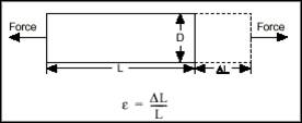

![]()
Zero Adjustment Circuit – The second method of balancing is to use a variable resistor or potentiometer to zero the bridge output voltage. By adjusting the potentiometer to control the bridge output, the initial output can be adjusted to zero.
Buffer Zero Adjustment – ​​The third method is similar to the software compensation method and does not directly affect the bridge. The buffer zeroing method adds an adjustable DC voltage at the amplified output of the zeroing circuit.
Connection of load cell or pressure sensor and measuring instrument
In this section we will study a measurement example using the NI cDAQ-9172 chassis and the NI 9237 C series strain scale blocks. The procedure is similar when using different measuring devices. 
After connecting the sensor to the measurement device, you can use LabVIEW graphical programming software to transfer the data to the computer for data visualization and analysis.