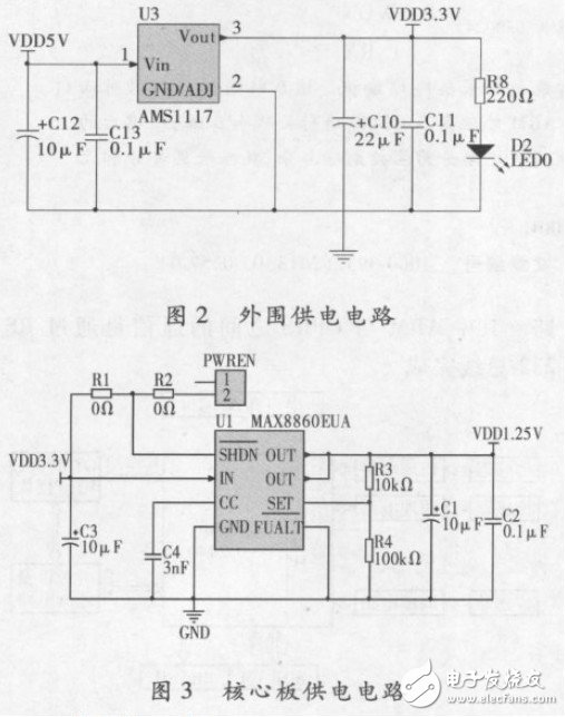
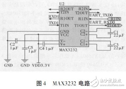
According to the characteristics of hydraulic system, an intelligent data acquisition terminal system based on ARM is designed. The system collects the oil pressure, flow and temperature signals through the sensor. The processed data is processed and compressed by the ARM processor S3C2440. The compressed data is transmitted remotely using the GTM900C wireless transmission module. The whole system hardware circuit is divided into a main control circuit part, a data acquisition part and a wireless transmission part. The hydraulic system has the characteristics of high power, fast response and high precision, and has been widely used in metallurgy and manufacturing. However, its faults are characterized by concealment, diversity, uncertainty and complex causality. It is not easy to find the cause after the fault occurs, and the failure will bring huge economic losses. In general, hydraulic systems can only be trouble-shooted by periodic inspections and maintenance. This method has a certain lag. Therefore, it is necessary to monitor the status data of the hydraulic system in real time and analyze it in time to reduce the failure rate and ensure the normal and continuous operation of the construction machinery. Traditional single-chip microcomputers have been widely used in data acquisition and processing. Although they are inexpensive and easy to develop, they are often difficult to meet engineering requirements in terms of storage space and network transmission. Therefore, the author used an ARM-based data intelligent acquisition terminal for the hydraulic system. The collection terminal collects three types of signals such as oil pressure, flow rate and temperature through sensors distributed throughout the hydraulic system, and filters and amplifies the collected signals, and then performs analog-to-digital conversion. After the data is analyzed, unified programming and compression are performed. Finally, the transmission is carried out through the communication module, and the data is transmitted to the local monitoring center for further fault diagnosis. 1 hardware overall structure The intelligent data acquisition terminal system adopts Samsung's ARMS3C2440 as the main control chip and GTM900-C GPRS as the communication module. The whole hardware system is divided into three parts: main control module, data acquisition module and communication module. The specific structure is shown in Figure 1. The main control module of the terminal includes a control chip circuit, a storage circuit, a power supply circuit, and a serial port and a JTAG interface circuit; the data acquisition module includes a sensor circuit, a signal conditioning circuit, and an 8-channel A/D conversion circuit; the communication module includes a GPRS chip and a peripheral circuit. The communication between ARM and GPRS is done through the RS-232 bus. 2 main control module design 2. 1 ARM chip introduction and working status setting The terminal system mainly uses the Samsung S3C2440 chip with ARM920T as the core. Although the chip has low power consumption and small size, it integrates rich on-chip resources. The main features are enhanced ARM architecture MMU, support WinCE, EPOC32 and LINUX; internal advanced microcontroller bus architecture; Harvard cache architecture; 10-bit 8-channel multiplexed ADC, can achieve a maximum conversion rate of 2. 5MHz 500kS / s under the A/D converter clock. The power supply of the main control module is divided into 3. 3V system peripheral circuit power supply and 1. 25V core board power supply. 3. 3V system peripheral circuit power supply through AMS1117-3. 3V voltage regulator module to complete the conversion, the circuit shown in Figure 2; 1. 25V core board power supply using low dropout, low noise MAX8860EUA regulator chip, the circuit shown in Figure 3 Shown. The S3C2440 uses a 12MHz active crystal oscillator and can be up to 400MHz after multiplying by the on-chip PLL circuit. The on-chip PLL circuit has both frequency amplification and signal purification functions, so the system can obtain higher signals with lower external clock signals. The operating frequency avoids the generation of high frequency noise. The reset circuit uses the MAX811S chip. When the system power supply is lower than the system reset threshold ( 2. 93V), the chip will reset the system. 2. 2 serial interface circuit The commonly used interface of the RS-232C standard is a 9-pin D type. However, the most basic communication requires only RXD and TXD. However, since the high-low level signal defined by the RS-232C standard is different from the definition of the S3C2440 system, the two are Inter-communication requires level conversion. In the microcontroller, the 5V MAX232 is commonly used, and here is the 3. 3V MAX3232. The typical application circuit is shown in Figure 4. 2. 3 NOR FLASH interface circuit The memory chip used by NOR FLASH in the terminal system is HY29LV160, the storage capacity is 2MB, the working voltage is 2.7 ~ 3. 6V, and the working mode is 16-bit data width mode. It should be noted that when the pin NC is connected to a high level, it is a 16-bit data bit, and when NC is low, it is an 8-bit data bit. When the 16-bit data width is selected, it is half-word mode. At this time, the 16-bit data bus D0 ~ 15 is connected to the data bus DATA0 ~ 15 of S3C2440, and the address bus is A0 ~ 19 respectively connected to ADDR0~ 19 of S3C2440, half word The addressing range is 1MB for the mode and 1 &TImes for the 32-bit S3C2440; 2 = 2MB. 2. 4 SDRAM interface circuit The SDRAM is K4S561632, which has a storage capacity of 32MB, an operating voltage of 3. 3V, and a data width of 16 bits. According to the system requirements, a relatively complex algorithm operation is required, so a two-piece storage system is selected, and the storage space is 64 MB. The specific connection method is that D0 ~ 15 of the first slice is connected to DATA0 ~ 15, and D0 ~ 15 of the second slice is connected to DATA16 ~ 31, thus expanding 16 bits into a 32-bit data bus corresponding to S3C2440. For address lines, SDRAM uses a memory array, that is, each slice is divided into 4 logical banks, each bank is commonly addressed by 13 row address lines and 9 column address lines, and the accessible space is 4 &TImes; 213 &TImes; 29 &TImes; 2 = 225MB. The connection of the address lines is to connect two A0 ~ 12 and ADDR2 ~ 14 respectively, select the row and column signals through RAS and CAS, select the bank through BA0, BA1, and finally pass the CS general film. Choose to achieve 64MB addressing.
We have many new digital products with reasonable price and high quality.
Pop Socket:Pop, tilt, wrap, prop, collapse, grip, repeat! Secure grips for texting, calling, photos, and selfies.
Webcam Cover:webcam covers help protect you by keeping your webcam covered when not in use.simply slide to open and close the camera.
keyfinder:Anti-Lost alarm tracer function, you don't have to worry about lost. your mobile phone anymore.
mouse,etc...
welcome to inquiry!!!
Pop Socket,Metal Webcam Cover,Plastic Webcam Cover,Usb Cable Custom Usb Gift company limited , https://www.customusbgift.com
Compatible with all smartphones and tablets!
Works in landscape/portrait modes for watching videos, web surfing, texting, gaming, group photos, FaceTime, and Skype.
Allows your hand to relax while securely holding your phone or tablet. Strong adhesive, sticks to most devices and cases.
Usb Cable:all our cable are available for iPhone and Android /Type-C.