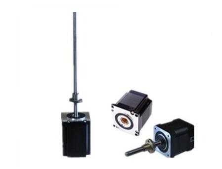
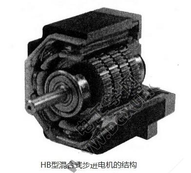
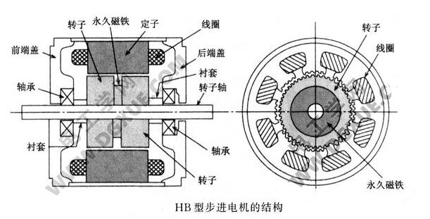
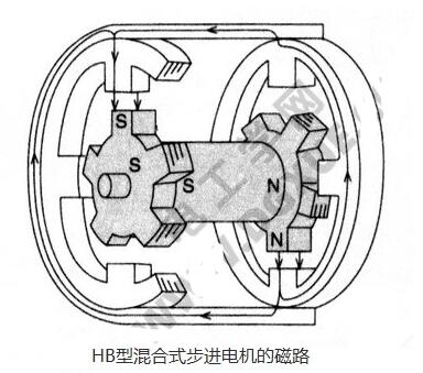
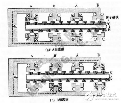
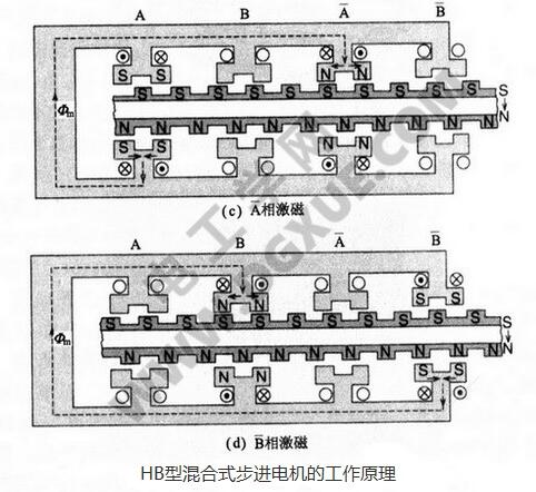
There are three types of hybrid stepping motors: permanent magnet (PM), reactive (VR) and hybrid (HB). The reactive step is generally two-phase, the torque and volume are small, the step angle is generally 7.5 degrees or 1.5 degrees; the permanent magnet step is generally three-phase, which can achieve large torque output, and the step angle is generally 1.5. Degree, but the noise and vibration are very large. Developed in Europe and the United States in the 1980s has been eliminated; hybrid stepping refers to the advantages of mixing permanent magnet and reactive. The hybrid (ie HB type) stepping motor has two-phase, three-phase, five-phase type. The rotor uses the same rotor regardless of the number of phases. This paper takes a two-phase HB hybrid stepping motor as an example. The name of the HB type is derived from its rotor structure. The rotor is a composite of a PM type permanent magnet stepper motor and a VR type variable reluctance reaction type stepping motor rotor. Therefore, this type of motor is also called a hybrid stepping motor. . This article mainly introduces the structure and working principle of the HB hybrid stepping motor, and follows the small series to understand. The HB type hybrid stepping motor has a structure in which two permanent magnet cylinders are axially sandwiched between two magnetic disks, and the outer circumferences of the two magnetic disks are the same, and the VR type is variable. The magnetoresistive reaction type stepping motor has the same rotor structure, and the teeth of the two discs are staggered by 1/2 pitch. The axial magnetization of the rotor cylindrical permanent magnet is N pole at one end and S pole at the other end. The rotor of the motor and the PM-type permanent magnet stepper motor rotor described above are structurally arranged. The N-pole and the S-pole of the PM-type rotor are distributed on the outer surface of the rotor. To improve the resolution, it is necessary to increase the number of pole pairs, usually 20 mm. Diameter, the rotor can be configured with 24 poles. If the number of poles is increased, the leakage flux will increase and the electromagnetic torque will be reduced. The N pole and S pole of the HB rotor are distributed on two different soft magnetic discs, so it can be increased. The number of poles of the rotor increases the resolution. The diameter of 20 mm can be configured with 100 poles, and the magnetic poles are magnetized to the axial direction. The N poles and the S poles are magnetized at the two poles after assembly, so the magnetization is simple. The stator pole corresponding to the rotor teeth has a small tooth having the same inner diameter as the rotor tooth pitch, and interacts with the magnetic flux of the rotor teeth at the air gap to generate electromagnetic torque. Such stepper motors for rotors have been widely used in the near future. This structure originated from Karl Feiertag of GE General Electric Company of the United States in 1992, and obtained the US patented generator. It is the same structure as the current two-phase HB type stepping motor. It was originally used as a low-speed synchronous motor. Later, the American Superior Electric Company and Sigma Instruments developed a two-phase HB with a step angle of 1.8° and a rotor number of 50. Stepper motor. As shown in the figure below, a cross-sectional view of a hybrid hybrid stepping motor with a stator of two-phase winding and a rotor number of 50 and 1.8° is shown. In order to increase the output torque, the axial length of the soft magnetic pole of the rotor is lengthened as much as possible. The following figure shows the structure of each type of HB stepping motor: The stator is evenly distributed with 8 magnetic poles (the main magnetic poles for placing the windings). The inner circumferences of the 8 magnetic poles are distributed with the same teeth as the rotor pitch, and the rotor teeth are distributed on both sides of the air gap. More rotor teeth than stator teeth. The coil is wound directly on the resin-molded slot insulation skeleton by a winding machine, and the coil is wound and mounted on the magnetic pole. The front and rear covers are made of cast aluminum material, and mechanical processing is used to ensure the concentricity of the bearing seat and the mounting stop. Generally, the HB type hybrid stepping motor has an air gap of 0.05 to 0.1 mm. Since the air gap is small, it is important to control the machining accuracy of each component. The rotor is installed in the stator and the front and rear end caps to ensure uniform air gap. The magnetization direction of the permanent magnet is axial. The N and S poles are magnetized at both ends. The direction of the magnetic field lines is as shown by the arrow. It is easy to understand and simplify the actual magnetic circuit. The stator has 4 main poles and 5 rotor teeth (as shown in the figure below), and the stator windings are omitted here. Since the magnetic flux of the permanent magnet of the rotor changes the flux in the stator, when the stator coil flows current, according to Fleming's left-hand rule (I is the current, B is the magnetic flux density, and L is the coil axial effective. Length) produces electromagnetic torque. The two magnets sandwich a permanent magnet, and the tooth positions of the rotor are different from each other by 1/2 tooth pitch. The magnetic flux of the rotor starts from the N pole, passes through the minimum air gap (where the stator teeth are opposite) to the stator magnetic circuit, and then returns to the S pole of the rotor. The magnetic circuit is indicated by the arrow. In the upper part of the rotor on the left side of the figure, the lower part of the rotor on the right side generates an attractive force, and the two sides of the shaft generate a moment (this force is an unbalanced electromagnetic force), and the rotation of the rotor is switched by the stator excitation coil to generate a rotational force. The clearance of the bearing can easily generate vibration. In fact, the main stator has 8 poles and the number of rotor teeth is even, in order to eliminate this unbalanced electromagnetic force. In fact, the stators opposite to the two rotor teeth are not separated into two in the axial direction, but are integrally formed by laminating silicon steel sheets. The following figure depicts the working principle of a two-phase HB stepper motor. The permanent magnet causes the rotor to generate N and S poles, and electromagnetic torque is generated by the attractive force and the repulsive force. The two-phase winding is assumed to be the A phase, the B phase, the "bar A" phase, and the "bar B" phase. For example, phase A and "bar A" are powered on, and the opposite magnetic field is generated according to the right hand spiral. Similarly, the same applies to phase B and "bar B". In the figure, a solid arrow indicates a rotor flux, and a broken line indicates a magnetic path Фm. From the axial view of the rotor magnet, the N pole of the rotor enters the stator downward through the air gap, and passes through the core of the stator to the upper stator pole through the core, and then returns to the S pole of the rotor through the air gap. The figure below fully illustrates the structure and working principle of the HB hybrid stepping motor. The middle of the rotor magnetic circuit is a permanent magnet, the lower side is the N pole, and the upper side is the S pole. The magnetic flux in the thickness direction of the magnet is from top to bottom. When the starting state (a) is the A phase excitation, the "bar A" phase has the opposite polarity, so it stops at the position shown in the figure, and the rotor corresponds to each half of the A phase and the "bar A" phase, forming a flux linkage Фm, such as The dotted line in the figure shows. Next, the exciting phase is switched to the state (b), the phase A excitation current is turned off, and the phase B excitation current is turned on, and the rotor is moved to the right by 1/4 of the rotor pitch to the position of the figure (b). In another step, the excitation phase is switched to the state (c), the B phase excitation is turned off, and the "bar A" phase excitation is turned on, and the rotor moves from the state (b) to the right by one step (1/4 pitch) to the state (c). )s position. Similarly, the excitation phase is switched to the state (d), the "bar A" phase is deactivated, and the "bar B" phase is energized. The rotor moves from the state (c) to the right by one step (1/4 pitch) to the state. (d) The location. In another step, the state (a) is returned, and the loop is continuously repeated. Transformer Service,Transformer Energy Monitoring,Transformer Monitoring System,Transformer Monitoring Hangzhou Qiantang River Electric Group Co., Ltd.(QRE) , https://www.qretransformer.com