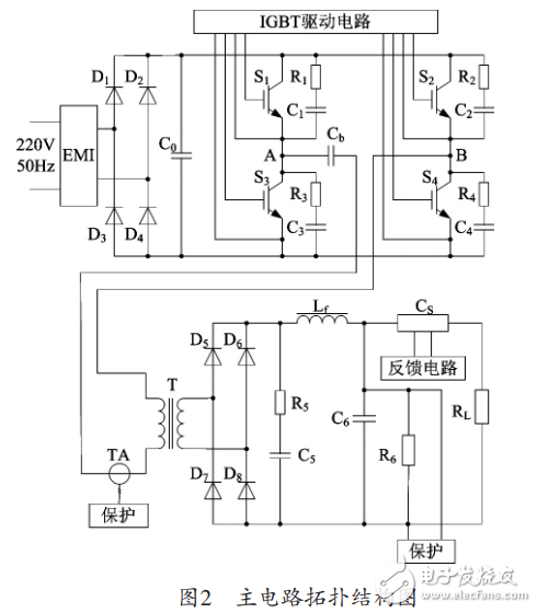
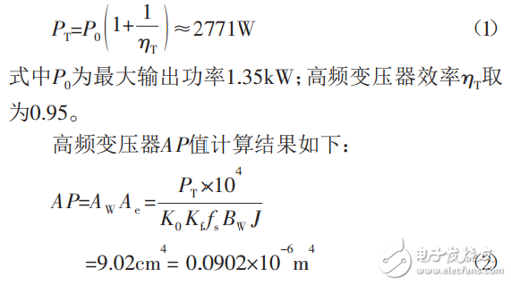
This paper introduces the design of high-current low-voltage DC switching power supply with SG3525 as the control core, full-bridge converter as the main circuit and output DC current of 45~90A. The output voltage can be automatically adjusted to adapt to load changes from 5~15V. To maintain a constant output current. The power supply is a constant current source working mode, and its output current can be continuously adjusted from 45 to 90A, and it works stably. The maximum output power is 1.35 kW. It adopts PWM control and the switching frequency is 30 kHz. Figure 1 is a power supply frame diagram, and a block diagram of the protection circuit is not shown. The single-phase 220V AC input is power-frequency rectified and filtered, and then supplied to the DC/DC full-bridge converter. At the moment when the power is turned on and the power supply voltage is turned on, since the initial voltage on the capacitor is zero, the initial charging of the capacitor will form a large instantaneous inrush current. The soft start circuit is used to prevent the instantaneous inrush current, improve the startup performance of the power supply, and protect the EMI filter. , power frequency rectification devices and capacitors to ensure that the switching power supply operates normally and reliably. The DC/DC full-bridge converter is mainly composed of a bridge inverter circuit composed of four switch tubes, a high-frequency transformer, an output high-frequency rectification and a filter circuit, and the bridge inverter circuit converts the direct current under the action of the control and drive circuit. It becomes a high-frequency square wave AC, and then it is stepped down by the high-frequency transformer and the secondary side is rectified and filtered to output DC. The power control circuit consists of a dedicated integrated chip SG3525 and its peripheral circuits to form a PWM modulation. After photoelectric isolation and power amplification, the full-bridge converter is directly driven. Since the power supply operates in a constant current mode and the current is large, the current sensor is applied for sampling. The output DC current is used as a control signal and fed back to the control circuit to achieve PWM modulation to achieve stable output current. The main circuit topology of the power supply is shown in Figure 2. Since the power supply has the characteristics of high current and low voltage, it is very sensitive to high-frequency interference signals and the inrush current at the moment of closing. Therefore, the EMI filtering is performed before 220VAC/50Hz AC rectification. Filtering greatly reduces the electromagnetic interference of the AC power input, while preventing harmonic crosstalk generated by the switching power supply to the input power supply. The high-frequency transformer is the core magnetic component of the DC/DC full-bridge converter. The parameter design of many other main circuit components depends on the parameters of the transformer, and it is very important to optimize the design. The high-frequency transformer design of the power supply adopts the AP method, and the AP refers to the product of the effective cross-sectional area of ​​the magnetic core and the effective window area of ​​the coil. The magnetic core adopts a pair of E-type soft ferrite. Considering the operating frequency of the converter, the magnetic induction BW of the magnetic core is designed to be 0.16T. According to the main circuit topology of the power supply, the calculation power of the high-frequency transformer is: Where AW is the core window area; Ae is the effective cross-sectional area of ​​the core; K0 is the window use coefficient, the typical value is 0.4; Kf is the waveform coefficient, the original secondary winding waveform of the transformer is square wave, taking Kf=4; Fs is the working frequency of the transformer (Hz); J is the current density of the winding wire, designed to be 400A/cm2. The AP value of the selected EE core should be greater than the calculated value. Because the secondary current is large, and the number of enameled wires is large, the window area is large. Finally, the PC40EE70 core with TDK is selected. The winding process adopts the original secondary side cross winding (two-stage all-inclusive) to achieve the tight coupling of the original secondary winding of the transformer and reduce the leakage inductance. The experimental results show that the design requirements are met. 48V25Ah Lithium Ion Battery,48V25Ah Lifepo4 Battery,48V Lithium Battery For Electric Scooter,48V25Ah Lithium Battery Pack Jiangsu Zhitai New Energy Technology Co.,Ltd , https://www.jszhitaienergy.com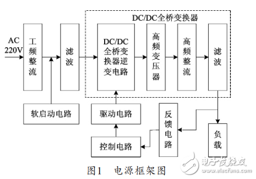
Design of high current and low voltage switching power supply based on SG3525 and DC/DC converter
introduction