When designing for specific power inputs and outputs, it is essential to understand the differences between inverters, converters, transformers, and rectifiers.
Inverter:
1. The direct current can be converted into alternating current through the oscillating circuit;
2. The obtained alternating current is boosted by the coil (the square wave AC is obtained at this time);
3. Rectify the obtained alternating current to obtain a sine wave.
AC-DC is relatively simple, we know that the diode has unidirectional conductivity. This characteristic of the diode can be used to form a bridge, so that the other end of the inflow is always flowing out, which results in a sinusoidal change of direct current. If smooth DC power is required and rectification is required, the simple method is to connect a capacitor. Inverter is a DC to AC transformer, which is actually a voltage inversion process with the Adapter. The Adapter converts the AC voltage of the mains grid into a stable 12V DC output, while the Inverter converts the 12V DC voltage output from the Adapter into a high-frequency AC high-voltage AC; both parts also use the pulse width that is currently used more. Modulation (PWM) technology. The core part is a PWM integrated controller, the Adapter uses UC3842, and the Inverter uses TL5001 chip. The TL5001 operates from a voltage range of 3.6 to 40V and features an error amplifier, a regulator, an oscillator, a PWM generator with dead-band control, a low-voltage protection loop, and a short-circuit protection loop. The following is a brief introduction to the working principle of Inverter:
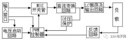
Input interface part: The input part has 3 signals, 12V DC input VIN, working enable voltage ENB and Panel current control signal DIM. VIN is provided by the Adapter. The ENB voltage is provided by the MCU on the motherboard. The value is 0 or 3V. When ENB=0, the Inverter does not work, and when ENB=3V, the Inverter is in normal working condition; and the DIM voltage is provided by the motherboard. The range of variation is between 0 and 5V. The different DIM values ​​are fed back to the feedback terminal of the PWM controller. The current supplied by the Inverter to the load will also be different. The smaller the DIM value, the larger the current output by the Inverter. Voltage Start Circuit: When ENB is high, the output voltage is high to illuminate the backlight tube of the Panel. PWM controller: It has the following functions: internal reference voltage, error amplifier, oscillator and PWM, overvoltage protection, undervoltage protection, short circuit protection, output transistor. DC conversion: The MOS switch tube and the energy storage inductor form a voltage conversion circuit. The input pulse is amplified by a push-pull amplifier and then drives the MOS tube to perform a switching action, so that the DC voltage charges and discharges the inductor, so that the other end of the inductor can be exchanged. Voltage. LC oscillation and output circuit: ensure the required voltage of 1600V to start the lamp, and reduce the voltage to 800V after the lamp is started. Output voltage feedback: When the load is working, the sampled voltage is fed back to stabilize the Inventer voltage output. In fact, you can imagine it. All of these electronic components require positive and negative electrodes, and resistors and inductors are generally not required. The diode may generally be broken because it is generally no problem if the voltage is normal, and the transistor will not be turned on. If the voltage regulator is reversed, it will be damaged. However, some circuits are protected by a single-directional diode protection. In the case of capacitance, the positive and negative points in the capacitor are electrolytic capacitors. If the positive and negative connections are serious, the outer casing will burst. The main component diode. Switching tube oscillating transformer. sampling. Adjust the tube. There is also the principle of the oscillating circuit resistance and capacitance isoparametric switching circuit.
The selection of the main power components of the inverter is crucial. The current power components are Darlington Power Transistors (BJT), Power FETs (MOSFETs), Insulated Gate Transistors (IGBTs) and turn-off thyristors ( GTO), etc., the more used devices in small-capacity low-voltage systems are MOSFETs. Because MOSFETs have lower on-state voltage drop and higher switching frequency, IGBT modules are generally used in high-voltage and large-capacity systems. The on-resistance of the MOSFET increases with the increase of the voltage, and the IGBT has a large advantage in the medium-capacity system. In the system with large capacity (above 100KVA), GTO is generally used as the power component. : FET or IGBT, transformer, capacitor, diode, comparator and master control such as 3525. The crossover inverter also has rectification filtering. Power size and accuracy are related to the complexity of the circuit. You can look at the phone charger, this is a small switching power supply!
There are two common types of inverters
• Pure Sine Wave Inverter (PSW) – The output of a pure sine wave inverter (as you may have guessed) is a pure sine wave. It is very difficult to get a perfect sine wave in the output, and the design for this purpose can be very complicated.
· Modified Sine Wave Inverters (MSW) – These inverters can use thyristors, diodes, and other passive components that generate rounded square waves, which are actually very close to the output pure sine wave. MSW can often be used in high power electromechanical equipment.
See related products:
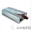
TN-1500-112F
converter
The converter is also only responsible for one job: converting AC power to DC power. But the term "converter" is very common and you may often see it being misused. For example, if someone says "DC AC converter," this means a logical meaning, although the correct term is "DC AC inverter." In the same situation, there may be a "DC DC converter". AC DC converters are also commonly referred to as power supplies.
See related products:
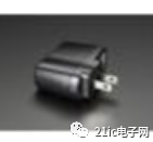
501
There are two common types of converters
Half-wave rectifiers – These are usually only used in low-power applications because their signals are inherently less consistent. Since half of the AC signal is lost, the output amplitude is about 45% of the input amplitude, which means that the power supply is heavily wasted during the negative half cycle of the input. Even if a large capacitor is placed for the load, there is still excessive ripple during the falling period of the AC input.
Full-wave rectifiers – Design engineers use full-wave rectifiers to handle this signal loss and get a much cleaner signal. They capture the positive and negative periods of the AC source for applications that require a smooth DC voltage source.
See related products:
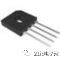
GBU15M-BP
You will usually see a full-wave rectifier circuit designed using one of these two methods: The first method is to use a multi-winding transformer that produces a pure signal that can then be smoothed through the capacitor on the load. The second method, called a full-wave bridge rectifier, can efficiently perform the work done by a transformer full-wave rectifier, but with a smaller configuration because no transformer is involved. Each option is essentially the same strategy as a half-wave rectifier, except that twice the AC input frequency and input almost never reaches zero.
This Wireless Bluetooth earbuds designed for business man, black color matching and simple appearance design, ultra-light weight makes easy to carry, deeply loved and sought after by business people.
The inner side is smoothly processed, and marked with [R" and [ L " labels in obvious positions to help identify. The line control is near the right earphone. the control area from left to right is previous song, power-on/ Play/pause/hang up the call, next song. The button is made of ABS. It needs to be long press for a long time when it is turned on or off.At the same time, the blue indicator light will always flash once when it is turned on. Three pairs of earplugs, large-medium-small, are included. The actual wearing comfort is not bad, and the physical noise reduction effect is not bad,It comes with a type-C data cable.
After turning on the Bluetooth headphones, the mobile phone can quickly search for Bluetooth. After the first match is successful, it can be connected to the mobile phone quickly next time it is turned on.
As a TWS earbuds, the sound quality is naturally one of the important criteria for judging its excellence. However, different people like different kinds of music, so they have different preferences for sound quality. For example, some people like the deep bass, some people prefer the shock of the high pitch, etc., so this piece is more subjective.
Small earbuds,HIFI earbuds,HiFi Ultra-light earbuds,Ultra-light Bluetooth Wireless earbuds
Shenzhen Focras Technology Co.,Ltd , https://www.focrass.com