Absolute rotary Encoder measure actual position by generating unique digital codes or bits (instead of pulses) that represent the encoder`s actual position. Single turn absolute encoders output codes that are repeated every full revolution and do not output data to indicate how many revolutions have been made. Multi-turn absolute encoders output a unique code for each shaft position through every rotation, up to 4096 revolutions. Unlike incremental encoders, absolute encoders will retain correct position even if power fails without homing at startup.
Absolute Encoder,Through Hollow Encoder,Absolute Encoder 13 Bit,14 Bit Optical Rotary Encoder Jilin Lander Intelligent Technology Co., Ltd , https://www.jllandertech.com
Circuit Operation Principle The vision health table lamp circuit consists of a power circuit, a timer, a photometric circuit, an LED flash circuit, a light control circuit, and a music circuit, as shown in Figure 9-69. 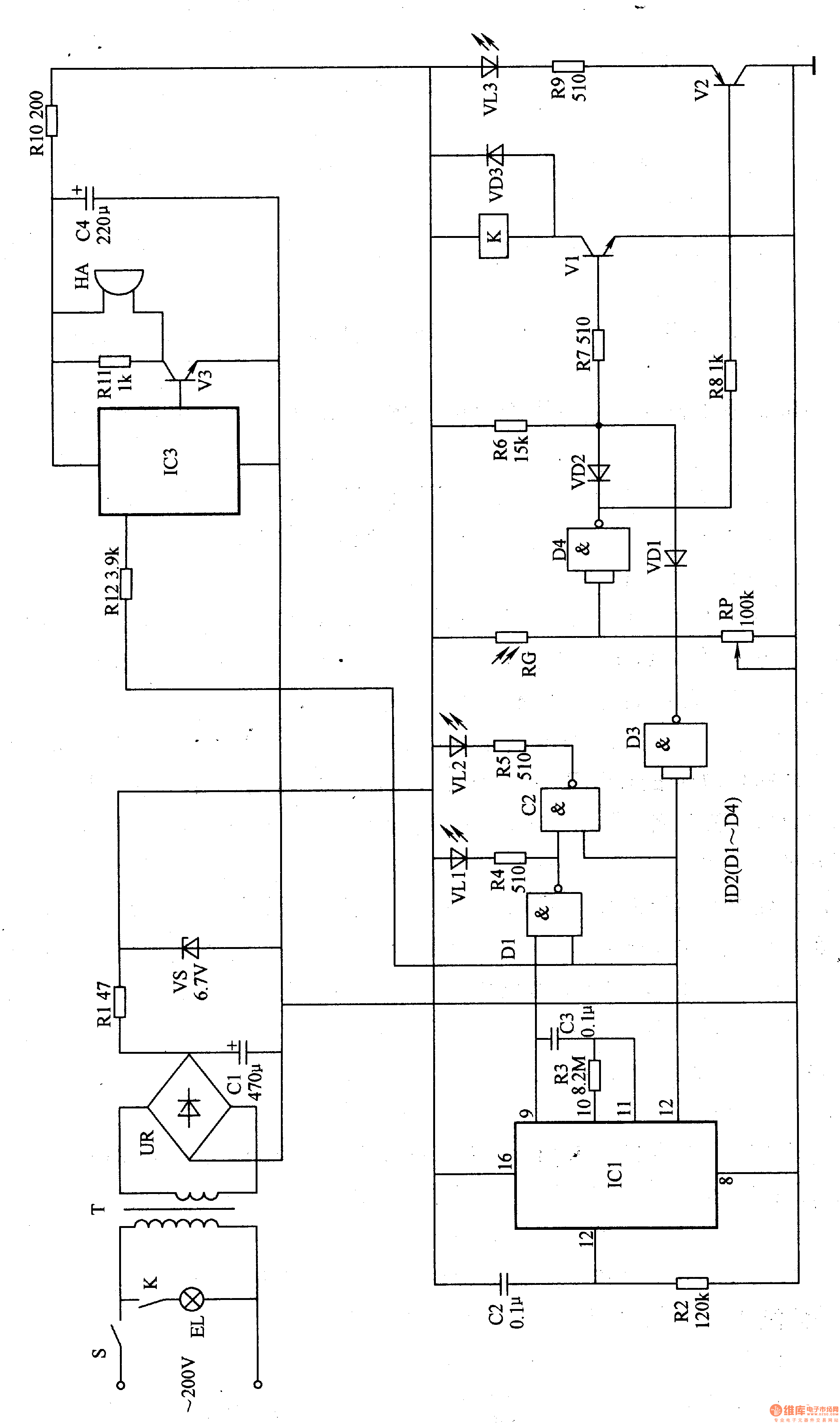
The power circuit is composed of a power switch S, a power transformer T, a rectifier bridge stack UR, a filter capacitor Cl, a current limiting resistor Rl, and a Zener diode VS.
The timer circuit is composed of a counter/divider integrated circuit IC1 with built-in oscillator, resistors R2 and R3, and capacitors C2 and C3.
The LED flash circuit is composed of NAND gates D1, D2, resistors R4, R5 and LED light-emitting diodes VLl, VL2 inside the four-NAND gate integrated circuit lC2 (Dl-D4).
The photodetection route photo resistor RG, the potentiometer RP, the NAND gate D4 inside the IC2, the resistor R8, the R9, the transistor V2 and the light emitting diode VL3 are composed.
The light control circuit is composed of a NAND gate D3, diodes VD1-VD3, resistors R6, R7, a transistor Vl, and a relay K.
The music circuit is composed of a music integrated circuit IC3, a transistor V3, resistors R10, R11, a capacitor C4, and a buzzer HA.
Turn on the power switch, AC 220V voltage after T step-down, UR rectification, Cl filtering, Rl current limiting buck and VS voltage regulation, provide 6V DC voltage for timer circuit, LED flash circuit, metering circuit and lighting control circuit . The working power of the music circuit is generated by the +6V voltage after R1O current limiting and C4 filtering.
After the power is turned on, the timer starts to count. At this time, the 1 pin of ICl outputs a low level, so that both DI and D3 output high level, VLl and VL2 do not emit light, VDl is in the off state, and Vl is saturated. K is energized and pulled, its normally open contact is turned on, and the desk lamp EL is energized and lit. At this time, the music circuit does not work, and HA does not sound.
When the timing time is over, the 1 pin of ICl outputs a high level, which makes Vl cut off, K is released, EL is extinguished, and VLl and VL2 alternately flash under the action of the 9-pin output pulse of ICl (the eye will rotate accordingly). Eliminate visual fatigue); IC3 is triggered by the high level of the output of IC1 pin 1, and the output music signal is amplified by V3, which drives HA to sound music, reminding the user to take a break.
When the ambient light is bright during the day, RG is in a low-resistance state, NAND gate D4 outputs a low level, VD2 is turned on, and Vl is in an off state. When the night or ambient light is weak, the resistance of RG becomes larger, so that D4 outputs a high level, VD2 is turned off, V2 is turned on, and VL3 is lit. At this time, if the ICI pin 1 outputs a low level, D3 outputs a high level, VDl is turned off, Vl is turned on, K is energized, and EL is lit.
Adjusting the resistance of the RP can change the sensitivity of the light control.
Component selection
Rl selects 2W metal film resistor for use; R2-Rl2 selects 1/4W metal film resistor or carbon film resistor for use.
Both Cl and C4 use aluminum electrolytic capacitors with a withstand voltage of 16V; C2 and C3 use monolithic capacitors or polyester capacitors.
VDl and VD2 select 1N4148 type silicon switch diode for use; VD3 selects 1N4007 type silicon rectifier diode for use.
VS selects lW, 6.2V silicon steady voltage diode, such as 1N4735 and other models.
VLl-VL3 selects high brightness LED of φ3mm.
UR selects the rectifier bridge stack of lA and 5OV.
Vl selects S8050 type silicon NPN transistor for use; V2 selects S9015 type silicon PNP transistor for use; V3 selects S9013 type silicon NPN transistor for use.
ICl selects CD4060 binary serial counter/divider integrated circuit; IC2 selects CD4001 or CC4011, MCl401l type four NAND gate integrated circuit; IC3 selects KD9300 or CW9300 type music integrated circuit.
K selects 4099 type 6V DC relay.
T selects 3W, the secondary voltage is 9-12V power transformer.
HA uses a piezoelectric buzzer.