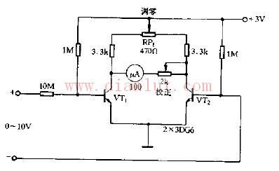
Below is a schematic diagram of a simple DC voltmeter circuit. This design is commonly used in basic electronics projects for measuring direct current (DC) voltage levels. The circuit typically includes components like resistors, a voltmeter, and sometimes a microcontroller or operational amplifier for signal conditioning. This simple DC voltmeter circuit schematic provides a clear view of how the components are connected and how the voltage is measured. It's ideal for educational purposes or for those looking to build their own low-cost measurement tools. Whether you're a student, hobbyist, or professional engineer, understanding this kind of circuit can be very helpful in developing your skills in electronics design and analysis. Tinned Copper Clad Copper TCCC Corrosion-Resistant Copper-Clad Tinned Wire,Copper-Clad Copper Tinned Wire Production,Copper-Clad Copper Tinned Wire Processing,Copper-Clad Tinned Wire changzhou yuzisenhan electronic co.,ltd , https://www.ccs-yzsh.com