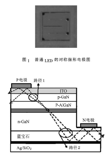
1. Introduction An important reason for the low light extraction efficiency of high-power LEDs is that the thickness of the LED substrate is relatively large. A large part of the light emitted by the active region is incident on the substrate layer and is absorbed by the substrate and the electrodes, thereby greatly reducing In order to improve this defect, the extraction efficiency of light, in order to improve this defect, in recent years, the use of an omnidirectional reflector (ODR) to reflect the light emitted from the active region to the substrate is a rising branch [1] —3]. Tu et al. [1] used ZnO contact as a mirror to reduce part of the light absorbed by the opaque electrode when the light source hits the top; Horng et al. [2] added a mirror between the Si substrate and the active region, and The p, n areas are roughened on both sides to increase the light, and the fabrication process is complicated. Li Yibo et al [4] use Si as the transfer substrate, Au as the mirror and bonding interface, and ITO as the buffer layer and window layer based on Au. /Au Directly bonded mirrors are metal mirrors that are essentially different from ODR and require bonding techniques in practice. The process is relatively complex; considering Ag / SiO2 as a mirror, incident light Whether the TE mode or the TM mode has a high reflectivity at different angles [5], so in this experiment, the existing chip is used, the sapphire substrate is first thinned, and then PECVD is performed on the sapphire substrate. Plated with a layer of SiO2 and Ag, it constitutes a white light ODR LED, the production process is simple, the light intensity is improved significantly, which is conducive to the actual production. The shape of the electrode used in the experiment is shown in Figure 1, and the cross-sectional structure of the ODR LED chip is shown in Figure 2. In Figure 2, the Mirror under sapphire substrate is Ag / SiO2 2. Experimental principle Figure 2 simulates the path traveled by light inside the ODR LED: When a forward voltage drop is applied to the p, n electrode, the p-zone and n-region electrons move toward the active region and radiate recombination. The light has two paths, one directly emits the path 1 as shown in Fig. 2, and the other one omits the omnidirectional mirror under the substrate, and reflects, and emits the path 2 from the top or side as shown in Fig. 2, thereby increasing the light emission. The path enhances the luminous flux and efficacy of the LED [6]. 3. Experimental samples The experimental samples of this batch use the chips produced by Yangzhou Huaxia Integrated Photoelectric Co., Ltd. The whole epitaxial wafer was tested and found to be basically identical after the test results were made into chips. The epitaxial wafer was made into a common LED chip and the other half was made. ODR LED chip, the size of the chip is 40 mil. Select the ODR LED chip in one unit as shown in Figure 3. Compared with Figure 2, it can be seen that the brightness of the chip is different. The chip is spot-measured by a semi-automatic needle measuring machine and the unit closest to the average point of the spot measurement (including one unit of the ODR chip and the common chip) is tested to form an LED sample. The two bare chips are before the package. The test results are shown in Table 1 and Table 2. It can be seen from the measurement results in Table 1 Table 2: The light intensity of the ODR chip is 1847 mcd higher than that of the ordinary chip by 244 mcd, which is a relative increase of 13.21%, which is due to the increase of ODR. Reflected light; When the same 350 mA operating current is applied, the voltage of the ODR chip is increased by 0.002 V from the normal chip voltage of 3.202 V. This error is small and negligible; other aspects of measurement, two chip tests The results are basically the same. 4. Test results and analysis 4. 1. Light color test results For the packaged samples, 7 common LEDs and ODR LEDs are selected. The different samples of the two types of LEDs are numbered separately. The fast light color and electric test of the LED is first carried out. The test instrument is the comprehensive test quantity of Hangzhou distant HAAS-2000 LED fast light color electricity. The system has a test temperature of 25 ° C and a test current of 350 mA. The test results of the two sets of LEDs are as follows. In Table 3, remove the No. 5 and Table 4 to remove the poor performance samples such as No. 5 and No. 7, and the two sets of samples are measured in reverse. The reverse voltage to the leakage current is - 5. 008 V. As can be seen from Table 3, the overall sample quality is good, the luminous flux is high, the average value reaches 76.62 lm, the luminous efficiency reaches 65.11 lm /W, and at the normal working current of 350 mA, the voltage is only 3. 362 V, color purity is 10.3%, but the color temperature is high, 7010 K; Table 4 shows that the LED after ODR LED treatment has obvious improvement in optical, electrical and color parameters, and the luminous flux reaches 81. 25 lm, the luminous efficiency is 68. 85 lm / W, which is 4. 23 lm, 3. 74 lm / W, which is a relative increase of 6. 04%, 5. 74%, the voltage is 3. 371 V. Only 9 mV is added. By comparing the dominant wavelength and color temperature of the ODR LED with the ordinary LED, we believe that the reflection of the ODR on the yellow-green light is stronger than the blue light, resulting in the increase of the light intensity of the yellow-green light in the white light spectrum of the ODR LED compared to the ordinary LED. Blu-ray, this aspect causes the color temperature of the ODR LED to be lower than that of the ordinary LED, which is reduced by 1804 K, which greatly improves the color temperature performance of the LED; on the other hand, the dominant wavelength of the ODR LED is red-shifted. Moreover, the color purity of the ODR LED is significantly higher than that of the ordinary LED. Ordinary LED is high, increasing by 8. 1%, and increasing by 78.64%. 4. 2. Spectral testing The luminescence spectra of the tested ODR LEDs and ordinary LEDs were tested. The results are shown in Figure 4. As can be seen from the figure, both samples produced two peaks with the same peak position and one peak at 445 nm. It belongs to the blue spectrum and the other peak is at 546 nm, which is the yellow-green spectrum. This is because the white LED samples are coated with YAG (yttrium aluminum garnet) phosphor on the LED blue chip. After the blue light excites the phosphor, it can produce typical 500-580 nm yellow-green light, yellow-green light and blue light to synthesize white light. Using this method to prepare white light is simple, easy to implement and high in efficiency, and the capital investment is not large, so it has certain practicability. It can be seen from Fig. 4(a), (b) that the first peak of the ODR LED and the ordinary LED are located at 445 nm, and the FWHM of both LEDs is about 33 nm, but from the upper right corner of the figure. The relative spectral intensity shows that the blue-ray spectral intensity of the ODR LED is higher than that of the ordinary LED; the other peak position, both LEDs are at 546 nm, the FWHM of the ODR LED is 122. 0 nm, and the FWHM of the ordinary LED is 120. 43 nm. The FWHM of the ODR LED is slightly larger than that of the ordinary LED, and the improvement is still needed. The spectral intensity of the yellow-green light in the ODR LED is also higher than that of the ordinary LED, which is due to the reflection of the ODR. However, the ODR LED has a higher increase of yellow-green light than the ordinary LED. In blue light, we believe that the reflection intensity of ODR for yellow-green light in white light is higher than that of blue light, which makes the increase of yellow-green light in white light spectrum higher than that of blue light, which is the reason why red wavelength and color temperature drop are dominant.