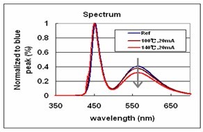
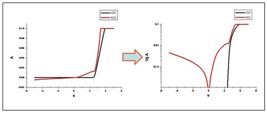
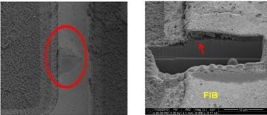
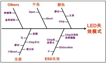
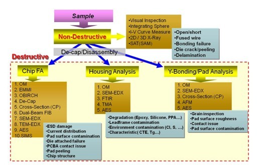
The light source of the LED is composed of a so-called III-V compound, which is a well-known epitaxial crystal chip. The solid compound itself is very stable and is not easily damaged under the conditions specified by the product. There is no chemical reaction in the application environment, so it has a long product life. However, in order for the LED chip to emit light, it is necessary to pass current from the outside. Therefore, a chip having a small size is generally attached to a specific stage (or a lead frame) and connected to a chip by a metal wire or a solder material. The positive and negative poles, and then the entire stage is covered with polymer material. This is the so-called packaging process. After this process, it becomes a common LED light particle on the market. In actual application, several LED light particles are assembled into modules as needed, and finally combined with other functional modules to become a terminal product. As can be seen from the above, the failure of an LED product may originate from any part of the product, so it must be stripped to find the true cause of failure. In view of the failure from the LED lamp particles, the LED chip itself is strong in the complete LED lamp grain, but the package material of the package chip is susceptible to damage. Therefore, the failure of the LED lamp grain can be attributed to the packaging material. Caused by damage or deterioration. To fully understand such failures, involving expertise in the fields of optics, chemistry, materials science, and electronic physics, and with sophisticated instruments and rich practical experience, we can confirm the failure point and derive the true cause, and then propose improvement measures. . When the company's LED products were tested for failure, the company found many general-purpose LED failures and developed corresponding analytical methods. This article will share the experience of serving LED customers over the past three years: 1. No light: This kind of failure means that the LED does not emit light at all when it is energized. In general, the "open" on the conductive path is one of the main causes of this type of failure. The method of confirming the open circuit is also very simple, and can be verified by a common three-meter. However, in order to find the break point, further analysis is necessary. For example, X-ray can be used to confirm whether the wire is broken or detached, and the structure of the cross section can be observed by SEM (scanning electron microscope) to check the defect of the die-shaped portion. Wait. The second main cause of this type of failure is "short". This is because the current does not pass through the LED chip, but flows through the "next door", so the LED lamp particles naturally do not emit light, such as: due to electron migration. Abnormal diffusion of electrode metal atoms, such as indium tin oxide (ITO), silver, or barrier metals in GaN/InGaN diodes, can occur due to mechanical stress, high current density, or corrosive environments. Other reasons may be wire shifting, adhesive gelling, etc. This failure must be determined by the IV curve (current-voltage diagram). As the failure point cannot be checked from the appearance, it needs to be confirmed by X-ray; or the chemical solution is used to remove the LED package material. Check optically (OM) or electron microscopy (SEM). Short circuit climbing open circuit broken line 2. Discoloration: This kind of failure means that the appearance color or the transparency of the rubber is different from the new one when the LED is not lit. It can be seen with the naked eye, usually after the product is used for a period of time or after the reliability test is completed. In general, the color-changing area can be roughly divided into two types: lead frame or encapsulant. If it occurs in the lead frame, it is usually because the surface reacts with the chemical substances in the environment, such as oxidation or vulcanization. Relying on the component analysis, the instruments that can be used include EDS (Energy Dispersive X-ray Spectroscope), XPS (X-ray Photoelectron Spectrometer), AES (Augur Electron Spectroscope), and the like. If the rubber used for packaging is discolored, it is a deterioration phenomenon of the polymer material. For example, the epoxy resin is susceptible to high temperature or ultraviolet light and turns yellow. Therefore, the white LED is replaced by a rubber. Special attention should be paid to the analysis of such failures. Because the rubber material itself has a certain transparency, sometimes the discolored lead frame is misidentified as the discoloration of the rubber material due to being covered by the rubber material, leading to the wrong direction of improvement. Bracket discoloration 3. Light decay: This failure means that the light intensity emitted by the LED is lower than the new one. As mentioned in the previous section, the degree of light attenuation has become an important indicator for judging the life of LED lighting products, so the analysis of such failures is very important. On the whole, the analysis of this type of failure is very complicated, because there are many factors affecting the light intensity, such as chip deterioration, deterioration of the reflector cup, delamination between the glue and chip, decreased transparency of the glue, and increased resistance of the wire joint. Thermal resistance is too high, etc. If it occurs in white LEDs, the problem of deterioration of fluorescent powder should also be considered. White LEDs usually use one or more kinds of phosphors, which are attenuated and reduced by heat or moisture. Efficiency leads to a change in the color of the output. Analytical methods include: non-destructive testing, such as visual inspection, LED electrical curve, optical characteristics of the integrating sphere, etc., using the above data to comprehensively judge, one by one, when inferring possible causes, then destructive analysis, using samples The preparation technique produces a suitable analytical sample, and is supplemented with various instruments such as SAT (Scanning Acoustic Tomography) ultrasonic scanning, FTIR (Fourier Transform InfraRed) Fourier transform infrared spectrometer, TEM (Transmission Electron Microscope) transmission electron microscope, SEM (Scanning Electron Microscope) and so on can be verified to the true cause. White LED light attenuation analysis – yellow light intensity attenuation 4. ESD failure: This is a kind of chip damage caused by electrostatic discharge. This phenomenon is highly valued in MOS IC products. For LEDs, the gallium arsenide (GaAs) chip itself can conduct electricity in the past, so this kind of problem It is not common, but because white LEDs use non-conductive sapphire substrates, and the substrate and GaN and other materials will form internal defects (such as poor row) due to lattice mismatch, which is more sensitive to ESD damage. Electrostatic discharges can result in immediate failure of semiconductor junctions or permanent drift of characteristics and potential damage that can result in increased rates of attenuation. There are several phenomena that can be used to help determine if a chip is subject to electrostatic damage, such as a reverse bias leakage current increase, a chip only partial illumination, a local melting point on the chip surface, and so on. Sometimes, the degree of static damage at the beginning is not high, and the electrical characteristics, luminescence characteristics, and chip surface integrity of the LED are not abnormal, but the damage will gradually become apparent due to accumulation, and sometimes it may be possible to survive the entire product life. Cycle, once the production line is not equipped with static protection measures, the customer retreat rate of the products produced will be high and low. In the face of this phenomenon, the failure analysis may not be able to find the true cause, so the antistatic measures for the production line are well prepared. It is the best solution. ESD failure LED GaN material IV curve Electrostatic discharge damage 5. Others: Sudden failures are often caused by thermal stress. When the epoxy resin package reaches the glass transition temperature (Tg), the resin expands very quickly, creating mechanical stress at the location where the semiconductor and solder joints come into contact. Weaken or tear it off, and at very low temperatures it can cause cracks in the package. In addition, high-power LEDs are sensitive to current crowding. Uneven current density is distributed over junctions. Local hotspots may occur, and there is a risk of thermal burnout. If the heat transfer of the substrate occurs again, it will cause The problem has become more serious. This is common in holes in the solder material or in electron migration effects and Kirkendall voids, so thermal burnout is also a common failure mode for LEDs. Conclusion: The structure of LED lamp and chip is relatively simple compared with common ICs, but it involves light, electricity and heat at the same time. Therefore, the cause of failure is more complicated. The steps performed in failure analysis are more complicated. Diversified, at the same time, LED chip and package structure are not the same due to patents. The complexity of sample preparation required for analysis is much larger than that of conventional IC, so excellent sample preparation technology, complete analytical instrument and rich The comprehensive judgment of experience can be used to obtain the correct failure analysis results. LED failure cause fishbone diagram LED failure analysis process Edit: Sophy MAPP is colorless in both liquid and gas form. The gas has a pronounced acetylene-like or fishy odor at concentrations above 100 ppm, due to the addition of substituted amines as a polymerization inhibitor. Low molecular weight alkynes have strong odors. Mapp Gas is toxic if inhaled at high concentrations. Mapp gas is a mixture of various hydrocarbons, principally, methylacetylene , propadiene and Propane(MAPP). It produces a relatively hot flame (2,976°C) with a high heat release in the primary lame (inner cone) (15,445kJ/m 3 ), less than for acetylene (18,890kJm 3 ) but much higher than for propane (10,433kJm 3 ). The secondary flame (outer cone) also gives off a high heat release, similar to propane and natural gas. The combination of a lower flame temperature, more distributed heat source and larger gas flows compared with acetylene results in a substantially slower pierce time. Mapp Gas Mapp Gas,Mapp Gas Torch,Mapp Torch,Mapp Gas Temp ZHEJIANG ICE LOONG ENVIRONMENTAL SCI-TECH CO.,LTD. , https://www.ice-loong.com