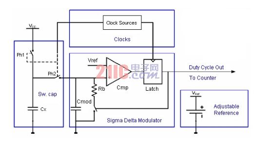
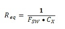
When you sit in a comfortable office, you can use your control buttons on the Crestron touch screen to perform a video conference with a foreign customer or branch office. When discussing the production situation of the products, you can click on the touch screen and the situation of the factories in other countries will appear immediately. You can immediately monitor the operation of the production department together with the conference personnel, check the security status of the core area of ​​the factory and discuss the improvement strategy. When talking about TV commercials, press a button and the ad will play on the touch screen instantly. Simply install the US Crestron remote control system, and the above situation is no longer an empty talk and can be implemented in your company. The basic ambient light control application includes a user interface or an ambient light sensor that can provide a control signal to the controller to change the brightness or color of the light. A block diagram of the basic ambient light controller is shown in Figure 1. Figure 1 : Block diagram of the basic ambient light controller Figure 2 : Ambient Light Control User Interface In general, people can select predefined light options through the user interface selection keys, but only from these predefined options can limit the ability of the user to control and configure various properties of the light according to their choices. . This article explores the user interface that uses capacitive sensors to control various light properties. The use of capacitive sensors not only gives the user interface a smooth and attractive edge, but also saves money and makes the solution more durable and immune to jitter. Some of the other features of the capacitive sensor include backlighting and backlighting close to the triggering device, which gives the system a new look and gives designers a lot of design margin. Capacitive sensing Capacitive sensing technology is a user input method. This technology is no longer just applied to the edge technology of a few selected products. It has been applied to thousands of products and millions of products. Design companies, manufacturers and semiconductor companies are investing heavily in order to take a bigger share of this rapidly expanding market and establish their leading position in the field. The technology itself has also been sustained in the process. development of. The core of these developments is the sensing method itself, which is the process used to measure and convert capacitance values ​​to digital values ​​and then process, control, and output the digital values. The most commonly used sensing methods are charge transfer, successive approximation, sigma-delta modulation, and mutual capacitance measurement. The CY8C21x34 – Capacitance Sensing CSD method available in the PSoC family of devices can be used in this application. This method uses a switched capacitor and delta-sigma technology to measure the capacitance of the inductor. The block diagram of Figure 3 illustrates the method of implementing CSD in CY8C21x34. Figure 3 : Block diagram of the use of CSD in CY8C21x34 In this method, the capacitance Cx of the inductor is simulated as a resistor using switched capacitor technology. The simulated impedance value can be obtained by Equation 1 below. Therefore, the modulator capacitor CMOD is charged by the dummy resistor. When the voltage across CMOD exceeds VREF, the output of the comparator is connected to the leakage resistor RB ground to bleed CMOD. This will put the output of the comparator at LOW and disconnect the resistor RB. This process will be repeated, the comparator will A series of pulses that turn on the counter are output. The output of the counter is a digital value corresponding to the inductor capacitance. When the sensor is touched with a finger, the capacitance of the sensor increases and Req is reduced. This will charge the CMOD faster. Since the leakage time is constant and the charging time is variable, the comparator output will be a series of pulses with different duty cycles. In this case, for longer periods of time, the output of the comparator will be in the HIGH state. Therefore, the output of the counter will change. This change in count from the counter will help detect the proximity of the finger. Using a pseudo-random sequence (PRS) generator to generate the switching frequency, the spectrum of the switching frequency signal can be expanded to reduce radiation and enhance noise immunity. User Interface The basic user interface of the ambient light controller controls the choice of red, green and blue colors as well as the intensity of the light. Therefore, it requires at least 4 capacitive buttons and 1 slider to control the intensity value of the light and the saturation of the color. The slider can be designed as a radial slider. The number of slider segments can be determined based on various factors such as the diameter of the slider, the number of revolutions up to 100%, the thickness of the outer cover, and the like. A typical sensor design layout is shown in Figure 4. This design arranges a capacitive switch for the red, green, and blue components of the light. In addition, it also arranged a brightness switch. The middle radial slider is used to control the color saturation and the intensity of the light according to the function selected by pressing the R, G, B or intensity switch. Figure 4 : Capacitive sensor user interface Cluster proximity sensing and backlighting Cluster proximity sensing and backlighting are value added features of this design. This feature allows the backlight of the interface to be activated as the hand approaches the device, allowing the user to find the interface in the dark. The CY8C21x34 has an analog multiplex bus built in to connect the sensors connected to each pin to the CSD clock. When used as a cluster approach, each segment of the radial slider is connected to the analog multiplex bus. This can be done with the API for the CY8C21x34 device in the following IDE (PSoC Designer). Whenever a hand is detected, the backlight is activated so that the user can find the interface. This feature also saves power by turning off the backlight after leaving the interface. The distance to turn on the backlight can be configured by adjusting the cluster sensor. The parameters used to control the starting distance (up to the limit) include Scan Speed, Ref Value, and Resolution. Scanning speed The scan speed is a parameter used in the CSD module to control the speed of the sensor scan. This parameter can help improve the signal-to-noise ratio (SNR). The scan speed determines the duration of the comparator output ON state, which in turn affects the system's count. Due to oversampling of the input signal, a lower scan speed provides a better signal to noise ratio. Lower scan speeds also provide better protection against power supply noise. The test results at various scanning speeds can be found in Appendix A. As can be seen from the figure, due to its low noise and high signal-to-noise ratio, a lower scanning speed should be used in the approach design. Therefore, in a cluster proximity sensor design, a lower scan speed should be used; when scanning the remaining sensors, a higher scan speed should be used. Resolution Due to the nature of the oversampling incremental measurement method, the noise will decrease with increasing resolution. The higher the resolution, the longer the measurement sensor takes longer, and the more noise is filtered out due to this integrated action. Please refer to Appendix A for the test results: Reference A voltage VREF corresponding to the value is applied to the inverting input of the comparator. The potential of the non-inverting terminal is also VREF due to the feedback effect of grounding the RB. When the potential is set small, the amount of charge stored by the inductor Will increase, for specific reasons, please refer to the basic capacitance equation of Equation 2. Therefore, lowering the reference value can improve signal quality and thus improve signal-to-noise ratio. Backlight LED LED backlight refers to the use of LEDs (light-emitting diodes) as a backlight for the liquid crystal display. Compared with the traditional CCFL (cold cathode tube) backlight, LED has the characteristics of low power consumption, low heat generation, high brightness and long life. It is expected to completely replace the traditional backlight system in recent years. The role of the backlight LED is to enhance the visibility of the dark interface. It can use either a single-color LED or a three-color LED. The three-color LED can accurately reproduce the controlled ambient light. For tri-color LEDs, a buck/boost configuration can be used to construct a closed-loop system as needed to control the color and intensity of the LED. in conclusion This article analyzes the advantages of using CapSense as a user interface to control ambient light. Design guidelines for implementing basic user interfaces and additional features are also discussed.
Led Strip Light is very soft, it can be curled, cut and extended. the led source and passages are completely covered in the flexible plastic, it is insulated, and it has the function of waterproof, strong weather resistance. It is difficult to break, with long life and flexible design, it is very convenient and used in many occasions.
Led Strip Light Led Strip Light,Led Strip Light Waterproof,Flexible Led Strip Light,220V Led Strip Light Zhongshan Laidi Lighting Co.,LTD , http://www.idealightgroup.com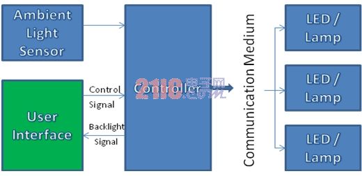
Most solutions available on the market use only a user interface or a combination of ambient light sensors and user interfaces to control ambient light. This type of user interface is shown in Figure 2. 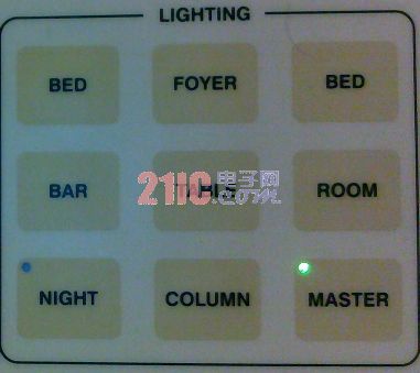
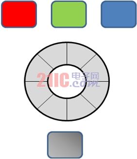
The radial slider is a combination of a plurality of capacitive sensors arranged in a ring shape. It is similar to a linear slider except that the ring slider has no start and end. Activating a sensor will activate the adjacent physical sensor halfway. The actual position of the finger on the slider is determined by calculating the position of the activated sensor core. ![]()
: 
Design and implementation of a lighting control user interface
0 times
Window._bd_share_config = { "common": { "bdSnsKey": {}, "bdText": "", "bdMini": "2", "bdMiniList": false, "bdPic": "", "bdStyle": " 0", "bdSize": "24" }, "share": {}, "image": { "viewList": ["qzone", "tsina", "tqq", "renren", "weixin"], "viewText": "Share to:", "viewSize": "16" }, "selectShare": { "bdContainerClass": null, "bdSelectMiniList": ["qzone", "tsina", "tqq", "renren" , "weixin"] } }; with (document) 0[(getElementsByTagName('head')[0] || body).appendChild(createElement('script')).src = 'http://bdimg.share. Baidu.com/static/api/js/share.js?v=89860593.js?cdnversion=' + ~(-new Date() / 36e5)];