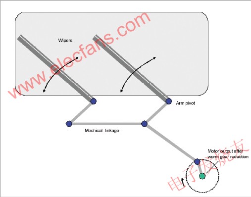
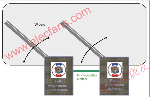
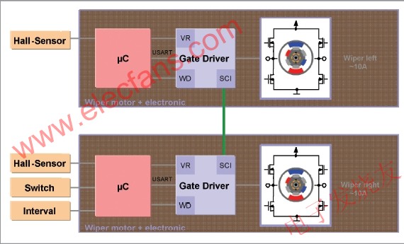
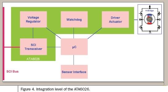
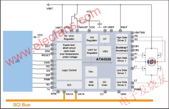
In the existing front-end double wiper system, the synchronization between the left and right wipers is achieved by mechanical connection (Figure 1). This is necessary because dirt on the windshield, the influence of the wind, or the condition of the wipers will make the left and right wipers behave differently. For many years, the automotive industry has been looking for an intelligent solution that can effectively reduce noise and reduce mechanical connection space. One solution is to replace the mechanical connection with an electronic system (Figure 2). In this architecture, each wiper is driven by a DC motor. The DC motor is controlled by a microcontroller and drive IC that can be installed directly inside the motor assembly. An interface is used to deal with the synchronization of the left and right wipers, so there is no need to use the mechanical connection on the traditional wiper system between the wipers, which significantly reduces noise and saves space. Due to cost reasons, the DC motor is used in the wiper system. A full H-bridge gate driver that supports PWM and four power MOSFET control directions can control this type of motor. ICs for such applications must be designed with high-voltage processes and must be suitable for use in harsh environments. In addition, large-capacity DC motor applications such as windshield wiper systems must use optimized communication interfaces. Because the electronic device of the wiper is usually very close to the car radio equipment, it is necessary to control the EMC radiation. The interruption of the car radio's electrical signal will make the car driver unbearable. Differential serial communication interface (SCI) transceivers can be used to reduce this type of radiation and improve EMC performance. The SCI transceiver is a differential device that can also operate in single-ended mode in systems with only one wiper. The SCI function of the gate driver makes it very similar to a LIN device. But compared with the standard LIN interface, its data transmission rate is faster, up to 100k baud. Each wiper module (Figure 3) consists of a microcontroller, a highly integrated gate driver and a DC motor. Multiple Hall sensors measure the position of the two wipers. The driver transmits the command to the microcontroller through the wiper switch. The electronic device can be installed close to the wiper motor, so no large space is required. The importance of low ECU current consumption is becoming increasingly prominent. To ensure that the quiescent current of the inactive IC is very low, a dedicated wake-up and sleep mode are required. The typical functional division of wiper applications is shown in Figure 4, which consists of a microcontroller, a voltage regulator that supplies power to the microcontroller, and other discrete components (such as Hall sensors). For safety reasons, a watchdog needs to be added to the system, because when driving in the rain, the wiper damage may cause danger. To further prevent system failures, ICs used in automobiles need to have many functions, such as thermal shutdown, overvoltage and undervoltage protection, and full protection against short circuits. They must also meet strict vehicle certification requirements (anti-conducted interference, EMC, and ESD protection) ). To solve these problems and meet the above functional requirements, Atmel has developed a highly integrated gate driver IC ATA6026. This gate driver IC includes a 5V / 100mA voltage regulator plus a watchdog, thereby reducing the number of external components required for small designs requiring a small PCB area, which is critical in electromechanical systems. This IC can realize motion control, so this function does not need to add any memory in the microcontroller. The window watchdog is triggered by the microcontroller switching from low level to high level through the WD pin during the window opening period. If the watchdog detects a window error, that is, it is not triggered when the window is opened or erroneously triggered when the window is closed, a reset pulse will be generated. The block diagram in Figure 5 gives the schematic diagram of the implemented functions and typical applications. The microcontroller controls the driving function of the IC by providing a PWM speed signal and a direction signal. Because the chip must drive the gate of the external H-bridge, it uses two push-pull drivers to control the two external power NMOS FETs used as high-side drivers, and the other two push-pull drivers are used to control the Two external power NMOS FETs for the low-side driver. The driver can be used with standard or logic level power NMOS FETs. The high-end control driver uses an external bootstrap capacitor to provide a voltage higher than the battery voltage 8V ~ 14V to the gate. Reverse control of the motor can also be achieved. By using a charge pump to power the gate of the high-end driver, it is possible to achieve a 100% duty cycle in both directions. To prevent high peak currents in the H-bridge, non-overlapping phases are used to switch external power NMOS transistors. The cross-conduction time is defined by the external RC combination circuit. Low power and low voltage drop on-chip voltage regulators are used for internal and external voltage sources. The external transistor as a power element helps reduce power consumption. In the inactive state, the device's sleep mode ensures very low quiescent current (typically 35 microamps). For the battery voltage of 6 ~ 9V, the adjusted output voltage is 5V ± 10%; when the battery voltage exceeds 9V, the adjusted output voltage is 5V ± 3%. To prevent damage to the external NPN tube and IC, a sense resistor can be used to detect the output current of the voltage regulator. If an overcurrent occurs, the voltage regulator can limit the current to a specific value. This means that if the function of the voltage regulator is changed to that of the current regulator, the output voltage will drop to an extremely low value. If there is a permanent conduction state (100% PWM, no bootstrap function is provided), the fully integrated charge pump can still power the gate of the external power MOSFET of the high-end driver. In addition, the gate of the external power NMOS for reverse battery protection can be powered by the charge pump output. As mentioned above, ECU applications need to have a sleep function to meet the requirements of low current consumption. In the ATA6026's sleep mode, you can use the pin EN or data to wake up the IC. Only a few modules are in the wake-up state (band gap, internal 5V voltage regulator with 100nF external DC-blocking capacitor, input structure for detecting the EN pin threshold, and wake-up module in the SCI receiving section). The default state at power-on is active mode. To achieve the transition between the two modes, three steps can be taken. In addition to activating / deactivating the EN pin, there is a second method to realize the wake-up function by using the SCI transceiver. In sleep mode, the SCI transceiver is partially activated and works in single-ended mode. If the activation function is implemented with SCI, the EN pin can be kept low without affecting the activation mode. Since the voltage regulator, motion control function, watchdog and communication interface are integrated on a single chip in a small QFN package, the total system cost is reduced, and in almost all motor drive applications that do not require adaptation, the output stage is The flexibility of plug and play is maintained. Motion control is part of the IC, and only the PWM speed signal and direction information must be provided by the microcontroller. Two diagnostic pins implement fail-safe functions. Agricultural Spraying Drone Pesticide Tank,Brushless Pump,Spraying Nozzle, Spraying Boom ,Folding Spraying Bar etc. Agricultural Spraying Drone Pesticide Tank,Brushless Pump,Spraying Nozzle,Spraying Boom shenzhen GC Electronics Co.,Ltd. , https://www.jmrdrone.com