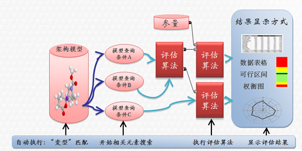
With the gradual strengthening of fuel economy, environmental protection and road safety requirements, the overall system optimization must be considered in the design of automotive electronic and electrical architectures, and it is necessary to improve development efficiency and shorten development time. At this time, the model-based method becomes very important . This method must be implemented with the help of tools. PREEvision is a system architecture design and optimization tool commonly used in OEMs. Its functions include requirements development, logic function design, network and component architecture, electrical system and harness design, and topology design. The tool covers from the conceptual prototype design stage to the detailed detailed design stage, and supports the detailed development and system specification formulation work of large engineering teams. This article relies on the tool to introduce the model-based design of the vehicle's electrical and electronic architecture. Development Process In order to ensure the quality of the electrical and electronic architecture system, the electrical and electronic architecture development needs to be developed according to a certain process. The electrical and electronic architecture development process mainly includes: determining the market positioning of the vehicle model, benchmarking analysis, demand development, architecture model design, and output scheme design files Wait for steps. 1) Market positioning The market planning department or model strategy department analyzes the market performance of the models to be developed through market research, investigates the needs of the sales population, and determines the positioning, shape, style, pre-sales area, etc. of the models to be developed according to the current market conditions and evaluation of the future market. Market prospects and other content. The positioning of the vehicle model at this time determines the complexity of the model of the subsequent benchmarking work and the development of the electronic and electrical system. 2) Benchmark analysis Before developing new models, it is generally necessary to select one or several existing models within the enterprise and competitor models with better market performance for a comprehensive benchmarking analysis to obtain relevant and non-functional features of the benchmarked model. The benchmarking analysis includes the following: electronic and electrical characteristics configuration; functional requirements specification; vehicle driving and operation measurement; CAN bus measurement; power supply system analysis; electronic and electrical topology analysis; ECU node technical specification analysis; electronic and electrical cost analysis and other aspects. When the workload of benchmarking is large, the results of benchmarking contain a lot of information. Generally, it is not stored in the form of a document, but the benchmarking data is stored in an enterprise database, such as the electronic and electrical system database provided by PREEvision. The results of benchmarking analysis can be used to analyze the shortcomings of existing models, propose new functional requirements and provide blueprints and materials for the design of new models. 3) Demand development Demand development work needs to be combined with the market positioning and benchmarking results of the vehicle model, as well as the relevant data of previous vehicle models. It mainly includes the determination of demand specifications and the formulation of evaluation criteria. To determine the demand specification, first of all, we need to collect the needs of customers and the requirements of laws and regulations, and initially determine the overall functional requirements; secondly, we will collect reference information of other models. Refer to the demand information of the benchmark model; again, you need to specify customer needs and regulatory requirements, and use technical language to describe, develop specific technical requirements documents, and form an Excel list or DOORS file. The evaluation criteria are jointly formulated by experts in related fields within the company. The formulation of evaluation criteria is divided into two aspects. One is to determine the various factors that need to be considered when evaluating the model, and the other is to determine the weight of each factor. After the modeling of the electrical and electronic architecture is completed, the model evaluation and variant comparison are performed according to the evaluation criteria. Figure 1 shows an example of the evaluation criteria. 4) Electronic and electrical architecture model design In the development process of the vehicle's electrical and electronic system, it will involve many aspects such as demand, functional design, network design, function distribution, and harness design, which will be jointly developed by different departments or engineering teams. In order to achieve a reasonable division of labor and collaboration in the parallel development process of multiple teams, the design of the entire electrical and electronic architecture needs to be carried out in accordance with the layered design (as shown in Figure 2). In the process of model development, continuous evaluation and optimization are needed to finally select the optimal design plan. a) Definition of requirements This layer needs to import the results of requirements development work-requirements specifications, and can also directly develop requirements development work at this stage. This layer is used to describe the functional requirements and non-functional requirements to be realized by the electrical and electronic system, and is the starting point of the electronic and electrical architecture design. b) Functional logic design This layer stipulates the logic implementation method of the entire system function. The content of the functional network layer includes functional modules such as logical sensors, functional blocks, and logical actuators, as well as information exchange interfaces between the functional modules. When the ports between the modules in the functional network layer are connected through the information exchange interface, the corresponding modules can exchange data and control information. In the functional network, users can see the logical relationship between functional modules. c) Hardware system design This layer mainly includes the network layer, the component layer and the principle layer. The network layer describes the logical connection between the components, such as: bus system, traditional connection, power supply and ground connection, these connections will be further refined in the subsequent circuit principle layer; the component layer describes the internal composition of each component The detailed information of its external interface; the line principle layer describes the specific implementation of the logical connection in the network layer, such as the specific wire, cable connection method, internal structure of the fuse relay box, etc. d) Harness layer design The logical and principle connection relationship is physically realized in the wiring layer. In this layer, the connection relationship of the line principle layer can be further refined in terms of wires and cables, and specific properties of the harness can be added to the model. In this layer, each piece of wire (or cable) and its corresponding connector have their physical properties (including information such as weight per unit length, cost, and overcurrent capability). Harness elements can form specific wire and cable layouts (including the layout of junctions and butt plugs, etc.) in the topology in the future. e) Topological layer design This layer describes the actual layout of the electrical and electronic system. The designer needs to determine the final installation position of each component and wiring harness according to the actual situation, and needs to set the specific length of the "line segment" between different installation positions. Then the statistical length of the entire wiring harness in the electrical and electronic system can be derived. 5) Output design files When the optimal plan is determined, the design specifications of the entire system, subsystems, and components can be output based on this plan. Distribute the specifications to relevant departments for specific design. Model application and advantages The electrical and electronic architecture model developed by layering is a system with rich attributes. A variety of applications can be applied to the model. The model-based development method brings many advantages to the development of vehicle electrical and electronic equipment. 1) Unified development tools In the development of traditional electrical and electronic architecture, a large number of documents are generated by basically relying on tools such as Excel, Visio, and Word. The model-based development method uses a unified development tool to integrate the relevant content of the electrical and electronic system into a tool to form an overall database to ensure data consistency. 2) Data tracking function The PREEvision tool uses a layered development method to establish an electronic and electrical architecture model. Through more than 30 information mapping methods across different technical levels, the mapping relationship between each level is achieved, making the electronic and electrical architecture model form a whole, ensuring the entire model The consistency of the data can be tracked at the same time, and the synchronization of design changes and the rapid location of error sources can be quickly achieved. 3) Consistency check Model-based methods can quickly perform consistency checks, can check the integrity and inconsistency of the entire structure; can test whether the model meets the overall needs and custom needs. With the support of tools, inconsistent elements can be quickly retrieved, making it easier to solve related problems. 4) Architecture evaluation In addition to meeting functional requirements, the system architecture should also meet specific performance requirements as much as possible. The model-based method can evaluate various parameters in the electrical and electronic model according to the specified evaluation algorithm and computing environment. Through the architecture evaluation, the estimated value or even the accurate result of the measurement index can be obtained, and then the result is compared with the predetermined reference value to quantitatively evaluate the performance of the architecture. 5) Variation management In the process of architecture development, multiple schemes are designed at the same time, and the method used for comparison and selection is called "variation". Model-based development can easily decompose the overall model into multiple model components, and create multiple alternatives for the model components and reintegrate them. The function of architecture evaluation can effectively evaluate the pros and cons of various schemes, and obtain a reliable electronic and electrical system architecture model. In addition, the model-based development method can well integrate the electronic and electrical systems of the entire vehicle, and can globally optimize the electronic and electrical equipment of the entire vehicle; the electronic and electrical models are very easy to reuse, which is conducive to the company's technology accumulation. Summary of this article The development process generally adopted in the model-based electrical and electronic architecture development method is as follows: determining the market positioning of the vehicle model, analyzing the benchmarking of the vehicle model, developing requirements, designing the architecture model, and outputting the design file. The model-based development method can use unified tools, ensure the consistency of the model data, can carry out convenient variant management, and can provide fast and automatic evaluation calculations, which makes the development of the electronic and electrical architecture of the OEM faster. Convenient. Product application: Switch UL,Decorative Switch UL,Electrical Switch UL,White Switch UL Hoojet Electric Appliance Co.,Ltd , https://www.hoojetgfci.com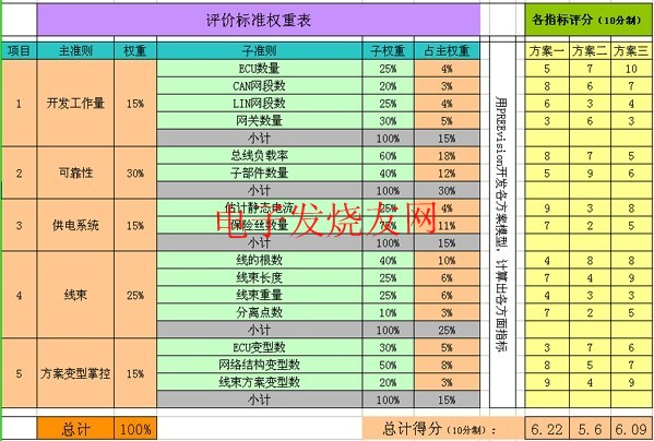


â– Products for commercial,household,lighting
Product features:
â– Good contact
--The contact point composite silver layer is designed to reduce
the contact resistance and reduce the temperature rise.
â– Ultra high strength,impact resistance and thermal stability
--The upper cover is made of high quality polycarbonate and the
bottom shell is made of PA6
â– Chemical corrosion resistance
-- Fingerprint-resistant zinc plated mounting brackets
â– Grounding
--One-piece grounding design