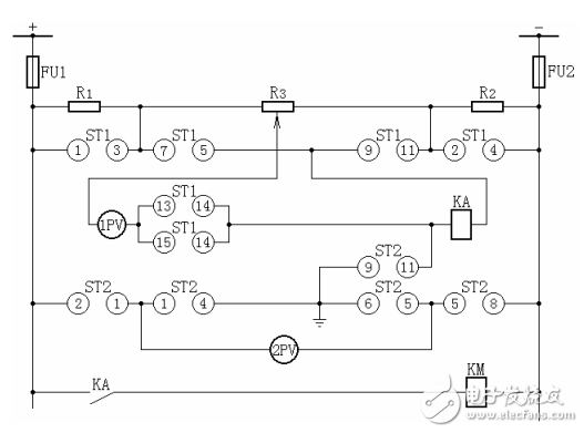
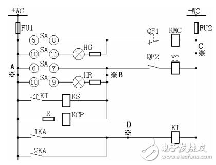
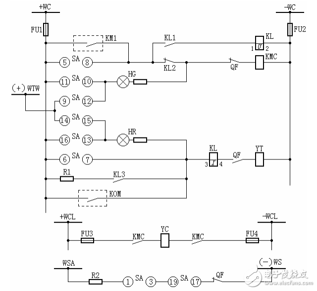
Secondary circuit Definition: All low-voltage circuits such as measurement circuit, relay protection circuit, switch control and signal circuit, operating power circuit, circuit breaker and electrical lockout circuit of isolation switch. An electrical circuit that is connected to each other by a secondary device to form a monitoring, control, regulation, and protection of the primary device is called a secondary circuit. It is a circuit that is connected in the electrical system by a secondary winding of a transformer, a measurement monitoring instrument, a relay, an automatic device, etc. through a control cable. It is used to control, protect, regulate, measure and monitor the working conditions of various parameters and components in the primary circuit. The circuits used to monitor the electrical connections formed by the meter, the control signal, the relay protection, and the automatic device are referred to as secondary circuits or secondary wires. Detailed secondary circuit 1. Figure 1 is the circuit diagram of the DC bus voltage monitoring device. Please explain its function. Answer: The DC bus voltage monitoring device mainly reflects the level of the DC power supply voltage. KV1 is a low voltage monitoring relay. The normal voltage KV1 is excited. Its normally closed contact is open. When the voltage drops to the setting value, KV1 loses its magnetism, its normally closed contact closes, and the HP1 light plate is bright, and an audible signal is emitted. KV2 is an over-voltage relay. When the voltage is normal, KV2 loses its magnetism. Its normally open contact is in the off position. When the voltage is too high, the KV2 is excited. The normally open contact is closed, the HP2 light plate is on, and the sound signal is emitted. . Figure 1 DC bus voltage monitoring device wiring diagram 2. Description Figure 2 The function of each component of the wiring diagram of the DC insulation monitoring device Answer: Figure 2 is the wiring diagram of the commonly used insulation monitoring device. When normal, the voltmeter 1PV is open, and the contacts 5-7, 9-11 of ST1 (1-31, 2-4 of ST1 are disconnected) and ST2 The contact 9-11 is turned on and the grounding relay KA is applied. When the insulation of the positive or negative pole drops to a certain value, the bridge is unbalanced to make KA act, and the signal is sent via KM. (If the insulation resistance of the positive and negative poles to the ground is equal, the KA cannot be operated regardless of the insulation drop, and it cannot be issued. Signal, this is its drawback). At this time, 2PV can be used to check to determine which pole insulation is falling (when "+" is grounded, 2-1, 6-5 of ST2 are turned on; when "-" is measured to ground, 1-4 of ST2 5-8 is turned on. Normally, the 2-1, 5-8, and 9-11 of the bus voltage meter changeover switch ST2 are turned on, and the voltmeter 2PV can measure the voltage between the positive and negative bus bars, and the indication is 220V.), If the positive pole is grounded to the ground, the ST1 I gear is turned on, the contacts 1-3, 13-14 are turned on, and the R3 is adjusted to the bridge balance voltage meter 1PV indicating zero volt; then ST1 is thrown to the second gear, at this time When the contacts 2-4, 14-15 are turned on, the total insulation resistance value of the DC system to the ground can be read from the 1PV. If the insulation of the negative pole to ground is lowered, first place ST1 in the second gear, adjust the 3R to the bridge balance, and then push ST1 to the first gear to read the total insulation resistance value of the DC system. If the positive pole is grounded, the positive-to-ground voltage is equal to zero. The negative pole indicates 220V to the ground, and vice versa when the negative pole is grounded. The voltmeter 1PV is used to measure the total insulation resistance of the DC system, and the resistance scale is drawn on the disk surface. Since there is an artificial grounding point in the insulation monitoring device, in order to prevent other relays from malfunctioning, the current relay KA is required to have a sufficiently large resistance value, generally 30 kΩ, and its starting current is 1.4 mA, when any one of the insulation resistances When it drops to 20 kΩ, it can send a signal. There are two cases of ground insulation degradation and grounding. Figure 2 DC insulation monitoring device wiring diagram 3. According to Figure 3, respectively, point A and point C; point B and point C; what is the danger when grounding occurs at point A or point B or point A and point D simultaneously? A: The DC system has an important position in the substation. To ensure the long-term safe operation of a substation, there are many factors, and the insulation problem of the DC system cannot be ignored. The DC system of the substation is more complicated. It is connected to the terminal block, terminal box and operating mechanism box of the outdoor power distribution device through the cable trench. It is more likely to be grounded due to cable damage, insulation aging, moisture, etc. When grounding, since there is no short-circuit current, the fuse will not be blown and can continue to operate, but it must be discovered and eliminated in time. Generally, the insulation resistance values ​​of various small busbars, terminal loops, and secondary cables to the ground of the DC system are required to be measured by a 500V shaker to be no less than 0.5 MΩ. The insulation of the DC link must be monitored frequently. Otherwise, it will bring a lot of insecurities to the operation. Take the example of Figure 3 to illustrate the hazard of DC grounding. When there is a grounding at point A and point C in the figure, it is equal to +WC, -WC forms a short circuit through the earth, which may cause the fuses FU1 and FU2 to be blown and lose the protection power; when point B and point C are grounded at the same time When it is equal to short circuit the trip coil, even if the protection is normal, the YT trip coil is short-circuited. Even if the protection is normal, the YT trip coil will not start, and the circuit breaker will not trip, so it will be tripped in the case of fault; When point A and point B or point A and point D are grounded at the same time, the protection will malfunction and the circuit breaker will trip. The hazard of DC grounding is not only the points mentioned above, but also many, which are not introduced here. Because DC grounding will cause many harms, a device for monitoring the insulation condition of the DC system is specially designed to prompt the DC system to the duty personnel in time for quick inspection and processing. Figure 3 DC grounding diagram 4, according to Figure 4 with a light monitoring circuit breaker control circuit diagram (electromagnetic operating mechanism) to explain the name of each component, the process of action Answer: In the figure: +WC, -WC - control bus; FU1, FU2 - fuse, R1-10/6 type, 250V; SA - control switch, LW2-1a.4.6a.40.20.20/F8; HG — green signal luminaire, XD2 type with 2500 Ω resistor; HR — red signal luminaire, XD2 type with 2500 Ω resistor; KL - intermediate relay, DZB-115/220V type; KMC - contactor; KOM - protection outlet relay; QF - circuit breaker auxiliary switch; WCL - closing small busbar; WSA - accident tripping small busbar; WS - signal small busbar; YT—circuit breaker trip coil; YC—circuit breaker closing coil, FU1, FU2—fuse, RM10-60/25 250V; R1—additional resistance, ZG11-25 type, 1Ω; R2—additional resistance, ZG11-25 type , 1000Ω; (+) WTW - flash small bus. (1) "After tripping" position When the handle of SA is in the "tripping" position, when the circuit breaker is in the trip position, its normally closed contact is closed, +WC via FU1 → SA11-10 → HG and additional resistance → QF (normally closed) KMC coil → FU2 →- WC. At this time, the green signal light circuit is turned on and the green light is on, which indicates that the circuit breaker is in the position after the trip, and that the power supply, the fuse, the auxiliary contact, and the closing circuit are intact, and the closing operation can be performed. However, the KMC will not operate because the voltage is mainly dropped on the HG and the additional resistor. (2) "Preparation and closing" position When the handle of the SA rotates 90o clockwise to the "pre-closed" position, SA9-10 is turned on, and the green light HG loop is guided by (+)WTW→SA9-10→HG QF (normally closed)→ KMC→FU2 →-WC The green light flashes and the preparatory closing signal is issued, but the KMC still does not start because there are HG and R strings in the loop. (3) "Close" position When the handle of the SA is rotated clockwise 45o to the "closed" position, the SA5-8 contact is turned on, and the contactor KMC loop is +WC → SA5-8 → KL2 (normally closed) → QF (normally closed) → The KMC coil →-WC is turned on to start, closing its contacts in the closing coil circuit to close the circuit breaker. After the circuit breaker is closed, the QF normally closed contact opens and the normally open contact closes. (4) "After closing" position After releasing the hand, the handle of the SA is automatically rotated 45° counterclockwise, returning to the vertical position (ie “after closingâ€), and the SA16-13 contact is turned on. At this time, the red light HR circuit is turned on by FU1→SA16-13→ HR→KL coil→QF (normally open)→YT coil→FU2→-WC, and the red light is on, indicating that the circuit breaker is in the closing position and indicating the trip. The loop is intact and can be tripped. (5) "Prepared Trip" position Turn the SA handle counterclockwise 45° to the “trip†position, SA6-7 is turned on, HR and R are shorted, and the +WTW→HR→KL→QF normally open contact→YT→-WC circuit, red light Flash, send a ready-to-close signal. (6) "Trip" position Reverse the SA handle counterclockwise 45° to the “trip†position, SA6-7 is turned on, HR and R are shorted, and the YT is excited by +WC→SA6-7→KL→QF normally open contact→-WC The circuit breaker trips. After the circuit breaker trips, its normally open contact opens, the normally closed contact closes, and the green light is on, indicating that the circuit breaker has been tripped. After the handle is released, the SA is reset to the “tripped†position. When the circuit breaker is manually or automatically reclosed on the faulty line, the protection device will trip. If the operator throws the control switch in the "closed" position (SA5-8 contact is closed), or the automatic device contact KM1 If it is not returned, the breaker SA5-8 will be closed again. Because the line is faulty, the protection and the action trip, resulting in multiple "jumping one" phenomenon. This phenomenon is called "jumping." If the circuit breaker jumps, it will not only cause the circuit breaker to be destroyed, but also expand the accident. The so-called "anti-jumping" measure is to use the "anti-jump" locking device or the electrical "proof" in the control circuit. Jump "wire" to prevent the circuit breaker from "anti-jumping" measures. The control loop shown in Figure 4 takes electrical "anti-jump" wiring. Its KL is a jump lock relay, which has two coils, one current start coil, which is in the trip circuit; the other voltage protection coil is connected in parallel with the closing contactor coil through its own normally open contact KL1. In addition, the normally closed contact KL2 is also connected in the closing circuit, and its working principle is as follows: When the switch is closed with the control switch (SA) or the automatic device (KM1), if it is closed on the fault line, the protection will act and the KOM contact will close, causing the circuit breaker to trip. When the trip circuit is turned on, the KL current coil is energized, KL operates, its normally closed contact KL2 opens the closing circuit, and the normally open contact KL1 turns on the KL voltage self-holding coil. At this time, if the closing pulse is not released (if SA is not reset or KM1 is stuck, etc.), KL reliably opens the closing circuit so that the circuit breaker cannot be closed again. Only when the closing pulse is released (ie, KM1 is turned off or SA5-8 is turned off), the voltage of KL can be restored to the normal state after the power is turned off from the holding coil. The role of KL3 in the figure is to protect the exit relay contact KOM, preventing the KOM from being burned before the QF is opened. The function of the resistor R1 is to ensure that the signal relay can operate reliably when there is a series of signal relays in the protection outlet circuit. Figure 4 Circuit breaker control loop for light monitoring (electromagnetic actuator) Editor's comment: The biggest feature of the secondary circuit diagram is that it is very logical. The operation of its equipment and components is strictly in accordance with the order of design. Therefore, as long as you look at the picture, you only need to grasp certain rules: first time, second time; first exchange , after DC; first power, after wiring; first coil, rear contact; first up and down; first left and right. With more than 15+ yrs rich MFG experience, you can definitely trust in and cooperate with. infrared thermometers wholesale, forehead thermometer wholesale,wholesale thermometer suppliers TOPNOTCH INTERNATIONAL GROUP LIMITED , https://www.micbluetooth.com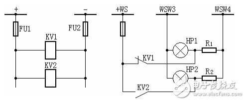
Provide you with the supply of Personal Protective Equipment. to help you safely get back to your daily routine.
Our products include pulse Oximeter Finger, Forehead Thermometer, Automatic foam soap dispenser, etc.
Our strict quality control protocol thoroughly vets every aspect of production, storage, and shipments all the way way to our end customers.