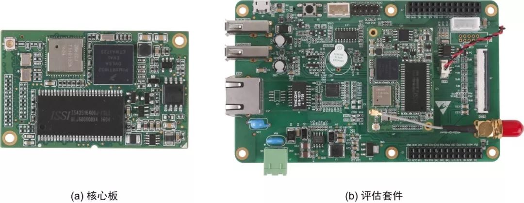
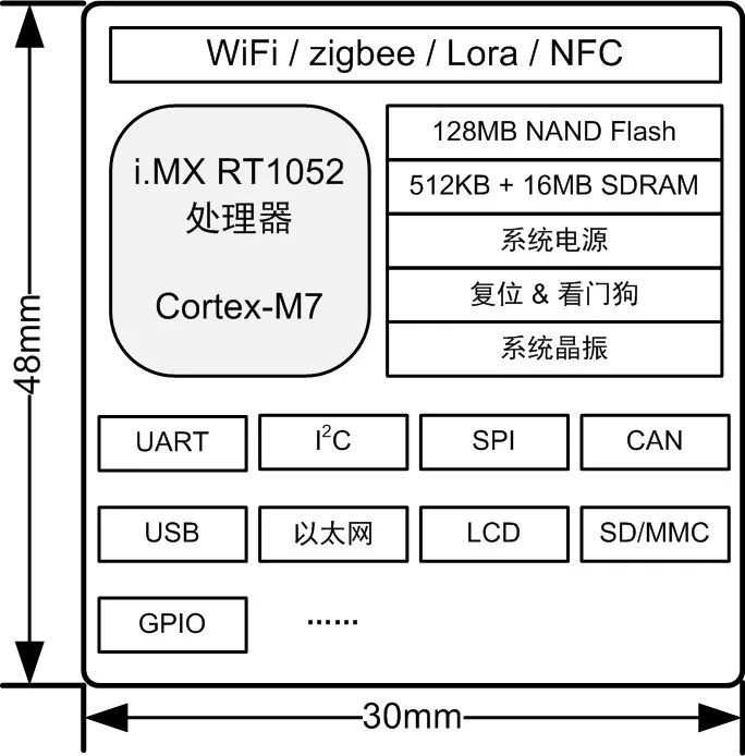
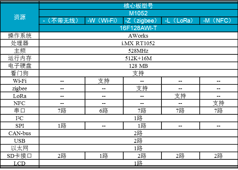
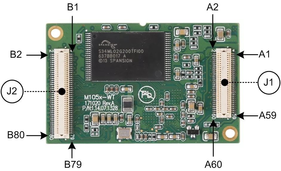
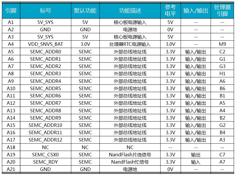
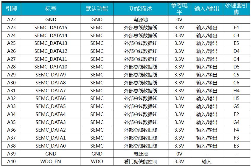
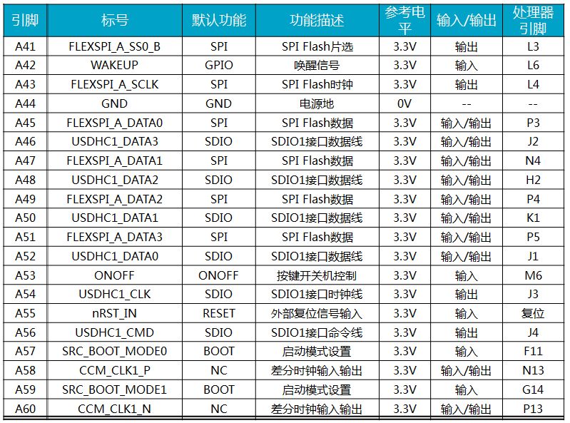
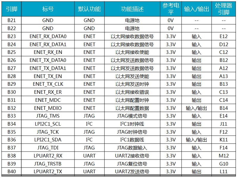
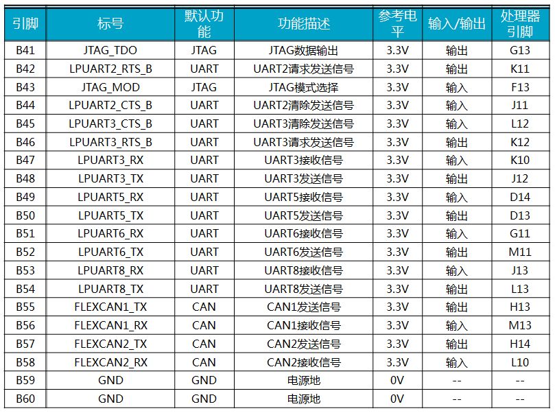
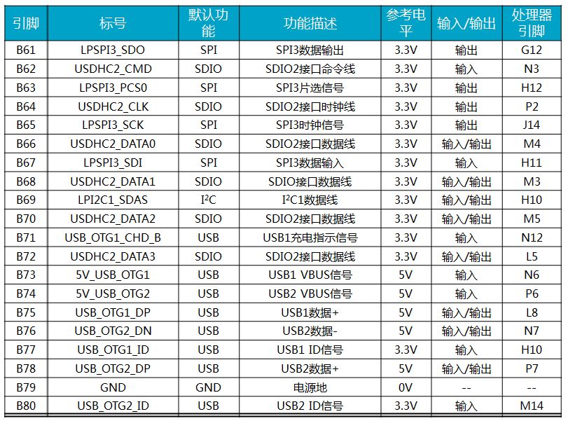
As the heart of thousands of smart IoT products, embedded processors are unique in their precise customization of functionality and performance. The gap between a single embedded processor and the ever-changing demand for the Internet of Things is continuously increasing. Different processors are needed to provide different power consumption requirements, different scalability, different computing performance, and different applications. Security to respond to different user experiences of the product. To meet this demand, Zhiyuan Electronics, with decades of leadership experience in providing MCUs and application processors for the industrial and IoT markets, has developed a new series of wireless core boards to meet the freedom of choice for product designers. Design brings innovative solutions without the choice of hardware that limits the innovation that may be achieved in their final design. 2.1 M105x Wireless Core Board (M7 Core) 2.1.1 Overview In today's smarter, connected world of technological innovations, smart hardware is no longer limited by the choice between MCUs and application processors, wired control and wireless communications. Embedded product designers prefer to be free to choose the solutions that will best innovate for their designs, rather than having hardware choices limit the innovations that may be possible in their final designs. They need to break the technology gap with a new class of cross-border embedded hardware that targets smart hardware, Industry 4.0, and evolving IoT applications that can provide design applications with high-performance processing capabilities A wide range of functional peripherals and a variety of network access interfaces, along with the MCU's ease of use, low power consumption, real-time operation, and low interrupt latency. M105x series wireless core board is also called M105x series cross-border hardware core board. It adopts NXP's Cortex-M7 core RT105x cross-platform embedded processor, clocked at up to 528MHz, integrates SDRAM, NandFlash, SPI Flash, and hardware gatekeeper. In addition to traditional communication interfaces such as UART, I2C, SPI, CAN, Ethernet, USB, and SDIO, the dog additionally integrates wireless communication modules such as Wi-Fi, Zigbee, LoRa, and NFC to achieve processor performance and control. Embedded hardware with communications, wired and wireless crossovers. The M105x cross-border hardware core board is not only cross-boundary in hardware, it also provides key availability features for embedded solutions: ease of use, low cost, real-time software and tool chain compatibility. The M105x Crossover Board provides a new IoT OS for the IoT operating system. It is designed to make it easy for developers to use these new crossover hardware without investing much effort in developing new software implementation tools or learning a higher level operating system. . The complete software and hardware architecture enables developers to focus on developing applications, greatly improving the efficiency of application development of smart hardware products, greatly shortening the product development cycle, and enabling products to be put into the market faster. AWorks IoT OS has developed a uniform interface specification, highly abstracted the functional components and peripheral devices built into various microprocessors, and is based on the principle of highly reusable software design and the idea of ​​only interface programming. Can achieve "a programming, lifelong use and cross-platform." The M105x core board can operate stably over an industrial temperature range and can meet a wide range of demanding industrial applications such as industrial control, field communications, and data acquisition. Figure 2.1 (a) shows the product diagram of the core board. See Figure 2.1 (b) for details of the evaluation board. Figure 2.1 Picture of M7 core board (M1052-W16F128AWI-T) and evaluation board (M105x-EV-Board) (according to actual product) 2.1.2 Product Features CPU: NXP RT105x series processor; Operating frequency: up to 528MHz; Onboard 16MB SDRAM; Onboard 128MB NandFlash or 8MB SPI Flash; Built-in power management unit PMU; Onboard AWorks system; Built-in independent hardware watchdog; Support various cloud protocols; Support multiple file system operations SD/MMC card, U disk read and write; Supports 1 way 10M/100M Ethernet interface; Supports 1 channel SD Card interface; Supports one USB2.0 Host and one USB2.0 OTG; Optional Wi-Fi, zigbee, LoRa or NFC-enabled wireless communication; Supports 6-way serial port (including one-way debugging serial port, serial port function has multiplexing); Supports 2 CAN interfaces; Supports 1 I2C and 1 SPI interface Support JTAG debug interface; 6-layer PCB process; Size 30mm×48mm; Operating voltage: +5V±2%. 2.1.3 Product Function Block Diagram The M105x series wireless core board integrates i.MX RT105x series processors, SDRAM, NandFlash, SPI Flash, hardware watchdog, Wi-Fi/zigbee/LoRa/NFC into a 30mm x 48mm module to make it Unmatched price/performance ratio, the functional block diagram of M1052 is shown in Figure 2.2. Figure 2.2 Functional Block Diagram of the M1052 Core Board 2.1.4 Product Selection The specific parameters of the M105x series wireless core board are detailed in Table 2.1. Users can select the appropriate core board for secondary development according to their project technical requirements. Table 2.1 Parameters of the M105x Series Wireless Core Board When enumerating the model of the core board, the model is divided into 3 lines for display. It can be seen that the prefix of the model is M1052, the suffix is ​​16F128AWI-T, and the different type of core board is distinguished by “-?†in the middle: - (without wireless) -W (Wi-Fi) -Z(zigbee) -L (LoRa) -M(NFC) A total of five core board products are listed in the table. Their corresponding complete models are: M1052-16F128AWI-T, M1052-W16F128AWI-T, M1052-Z16F128AWI-T, M1052-L16F128AWI-T, M1052-M16F128AWI-T. 2.1.5 I/O Information M105x Series Wireless Core Boards In order to cooperate with standard driver software development, the factory firmware of the product sets the default function for I/O. If you need to change the pin function attributes, the user can refer to the manual, carefully understand the driver architecture, and provide the SDK development kit. On the basis of self-revise the driver, adapt the required functions. After the configuration is complete, check that each pin configuration is correct and avoid driver conflicts. Figure 2.3 shows the schematic layout of the core board product pins. Figure 2.3 Pin arrangement of M105x series connector The core board uses two precision board-to-board connectors, J1 (A1 ~ A60) and J2 (B2 ~ B80), to draw processor resources from the back. The factory default functions of the corresponding pins of the J1 and J2 connectors are detailed in Table 2.2 and Table 2.3 respectively. Table 2.2 Pin definitions for the M105x wireless core board (J1) Table 2.3 Pin definitions for the M105x wireless core board (J2)
The main pain points in obtaining customers in foreign trade are fierce market competition, high customer acquisition costs, low customer stickiness, and single marketing methods. With the changes in the market environment, traditional marketing methods have been unable to meet customer needs. Enterprises need innovative marketing methods and technical means to improve customer stickiness and loyalty, reduce customer acquisition costs, in order to obtain more business opportunities in the fierce market competition.
banann Bossgoo(China)Tecgnology , https://www.cn-gangdao.com