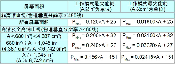
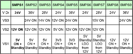
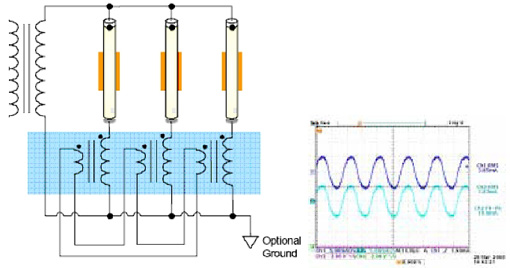
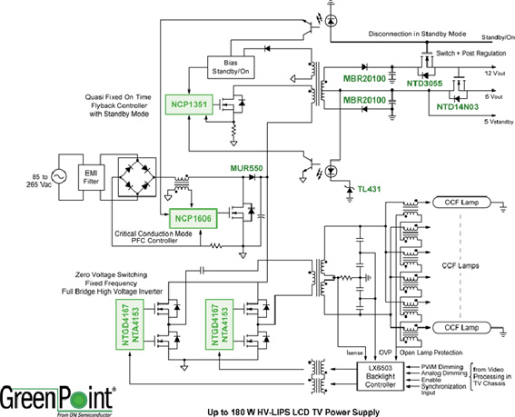
Mainstream LCD TV power supplies of 32 inches and larger require multiple voltage rails to power different system modules such as audio, backlight and signal processing. Among them, the signal processing board uses local linear and DC-DC converters to provide different low-voltage rails. For manufacturers, a universal power supply is typically used to support voltages from 90 to 265 Vac. This enables a single power supply design based on a specific TV size to be used in a range of different models to meet different regional market needs, streamlining logistics and reducing development costs. This article refers to the address: http:// If a certain type of LCD TV faces the global market and its power is higher than 75 W, it needs to comply with the European IEC61000-3-2 standard for harmonic reduction, which requires the use of an active power factor corrector. In general, the most power-hungry subsystem in a LCD TV is a backlight module. Most LCD TVs today use a cold cathode fluorescent tube (CCFL) array as a backlight. These lamps need to be driven by AC high voltage and require constant current flow to the lamp. Traditionally, the inverter is a separate module that is powered by a DC power supply rated at 24 V. In this approach, backlighting is required to be associated with LCD panels, and a power supply design can be used for panels from a variety of different vendors, simplifying LCD TV design, but this approach is less efficient and adds additional Power section (refers to 24V output). For example, the LCD TV's AC input voltage is boosted to 400 Vdc in the PFC section and then converted to 24 Vdc using a resonant (LLC) half-bridge. This 24 Vdc is then supplied to the inverter module, which converts from a DC low voltage to an AC high voltage above 1,000 V to drive the CCFL lamp. This multi-segment conversion process produces large losses and increases system cost. The high-voltage LIPS (HV-LIPS) architecture used in this reference design is designed to eliminate the 400 Vdc to 24 Vdc conversion section and power the inverter directly from the high-voltage power factor correction (PFC) input section to improve overall system efficiency. This requires the traditional power supply function to be integrated in the LCD TV in a direct high-voltage conversion mode to optimize the overall system solution. Traditionally, the standards of many voluntary and normative organizations around the world have focused on reducing the standby energy consumption of electronic products. Many international standards in the United States, the European Union and other places require 1 W for standby energy consumption of TV products, while China won the bid certification center ( CSC) requires 3 W. As LCD TVs become larger and larger, their energy consumption is getting higher and higher. As the market share of LCD TVs is getting larger and larger, the regulatory agencies are paying more and more attention to the cumulative impact of energy consumption on the grid in the working state of flat-panel TVs. For example, “Energy Star†released the energy consumption requirements for the third edition of TV products (see Table 1). Table 1: Energy requirements for the operating mode of the Energy Star 3.0 specification Key design goals Input voltage: universal input 85-265 Vac, 47-63 Hz System power Active Power Factor Correction (Active PFC) in accordance with IEC61000-3-2 · Maximum steady state energy consumption 50 W, peak 60 W ·12 V / 4 A peak ·5 V / 2.5 A peak · 24 V – MOSFE gate drive bias Flexible modification to support other voltage/current configurations • Standby input energy consumption (Pin) < 400 mW (5 V@10 mA) at 50 mW load Inverter power supply · Support 100 W power ·Strike voltage > 1,500 Vac, operating voltage > 800 Vac Fixed frequency inverters that can be adjusted in the 40-80 kHz range · Support digital and analog dimming · Ability to sync to video clock source PFC segment design The core of the high-voltage LIPS architecture is the active PFC front-end boost section. First, for power supplies with input power greater than 75 W, it is designed to meet the harmonic content requirements of the IEC61000-3-2 specification. Second, it provides a regulated 400 Vdc high voltage for the inverter section. In addition to powering the backlight, the PFC section also provides power to an isolated flyback switching power converter that provides all the power needed to perform functions such as control, interface, signal processing, and audio amplification in the LCD TV. And analog circuit power supply. Depending on the LCD TV's feature set and function, the power of this module may be between 30 and 60 W. To simplify the design and reduce the overall complexity of this power conversion section, this reference design uses ON Semiconductor's proprietary energy-efficient flyback controller NCP1351, which eliminates the need for dedicated standby power for most LCD TV applications. The NCP1351 was chosen because it uses the quasi-resonant fixed on-time (FON) control principle to reduce the switching frequency of the flyback converter as the load requirements become smaller. Two additional switches (on the secondary side) disconnect the mains load in standby mode, eliminating parasitic losses in standby mode. The PFC controller used in the PFC section is ON Semiconductor's NCP1606B, which is designed to operate in variable frequency critical conduction mode (CrM) and is the most suitable solution for 150 W power (<180 W) applications. More information on electromagnetic interference (EMI) design, specific control approaches, detailed design procedures, and test results for this PFC section can be found in Resources [1]. Flyback converter section for control, signal and audio functions Because of the use of specialized DC-AC converters to power CCFL lamps, flyback switching power supplies are used to power analog and digital modules for functions such as control, signal processing, and audio amplification. Due to the limited total power required (<60 W), it is possible to consider a flyback topology with standby mode without the need for a dedicated standby switching power supply, which increases the overall price/performance of the solution. To achieve this goal, an energy-efficient controller architecture is required under light load conditions. This flyback converter uses the NCP1351 PWM controller, primarily for off-line flyback power supplies with power below 60 W. The NCP1351 uses a quasi-fixed on-time technology. Different loads and different input voltages correspond to different turn-off times. When the load becomes lighter, the switching frequency is reduced and the switching loss is reduced. Therefore, power supplies using this approach naturally provide minimal standby power and optimize energy efficiency under other load conditions. As the frequency decreases, the peak current gradually decreases to about 30% of the maximum peak current, preventing the transformer from working mechanically. The risk of audible noise is also greatly eliminated, while also achieving good standby energy performance. Since the PWM controller operates at a quasi-fixed on-time, the switching frequency varies with the load. This flyback converter operates in discontinuous conduction mode (DCM) under light load conditions. As the load increases, the frequency also increases until the controller enters continuous conduction mode (CCM), while CCM optimization is used to provide extremely high efficiency. In addition, in LCD TV applications, achieving good cross-regulation is a design challenge because the tolerance is very strict (usually ±5%), and due to the large dynamic range of audio amplification, and the signal processing power load is based on the input video. The source changes and the dynamic work can vary widely. The typical output voltage and load range of this reference design reference type (SMPS1) is: · +5 V: 0 to 2.5 A ·+12 V: 0 to 4 A To improve overall cross regulation, the +5 V diode is connected to ground (GND) of the winding, while the +12 V winding is above the 5 V winding. In standby mode, the frequency of the switching power supply operates in the audio range. Therefore, depending on the transformer construction and mechanical design, there may be some audible noise. The most sensitive frequency range for most people is the 7 to 13 kHz range. This dedicated reference design is applied to a nominal standby load of 50 to 75 mW, so the standby frequency is less than 5 kHz. This reference design provides sufficient flexibility to accommodate multiple output configurations with minimal adjustments to the BOM. The NCP1351B flyback design provides the flexibility to support up to four unique voltage outputs. The standard configuration (SMPS1) used in this reference design has 5 Vdc and 12 Vdc inputs, as well as a 24 Vdc voltage output. Table 2 lists a variety of optional configurations that can be used to match different power mechanisms. Table 2: Flyback Converter Segment Standard and Optional Output Voltage Configuration High voltage backlight inverter power supply section 1) Comparison of half-bridge and full-bridge topology The high voltage inverter can be implemented in a half bridge or full bridge topology. There are a number of factors to consider when deciding which topology to use. Compared with the half-bridge structure, the full-bridge topology has many advantages, such as zero-voltage switching (ZVS) at a fixed operating frequency, reducing EMI and power loss, reducing MOSFET switching stress, and reducing heat dissipation. In addition, in the full-bridge topology, since the controller operates at a fixed frequency, it is possible to synchronize the switching frequency with the video frequency to avoid any possible backlight subsystem interference affecting the video image. 2) LX6503 backlight controller This reference design uses Microsemi's LX6503 backlight controller. The LX6503 is a high performance CCFL controller designed for LCD TVs and other multi-lamp LCD display systems. It has been specially optimized to be a cost-effective solution for high voltage inverter architectures. This controller provides a pair of push-pull PWM drive signals with sufficient capability to drive a push-pull half-bridge or full-bridge CCFL inverter with the addition of a simple external circuit. 3) CCFL drive and current balance Careful consideration must be given to CCFL lamp start-up and current balancing to have a reliable backlight system. The JIN balancer solution used in this reference design provides excellent lamp current balancing while also incorporating frequency sweeping to ensure reliable lamp start-up. Based on the electromagnetic coupling principle of the balance transformer, the JIN balancer generates an additional correction voltage to the lamp to equalize the lamp current. The basic configuration of this balancer network is shown in Figure 1. The serial loop of the balancer secondary winding equalizes the primary side current and provides a coupling mechanism between the lamp circuits. With such a coupling mechanism, if one of the lamps is not activated, the energy of the activated lamp will be automatically coupled to the primary winding of the unactivated lamp circuit, thereby increasing the lamp voltage and assisting its startup. As shown in Figure 1, the winding configuration of the balancer network is consistent regardless of the number of lights. In addition, one type of balancer transformer can accommodate almost any lamp size. These features make the JIN balancer solution very flexible for CCFL inverter applications. Figure 1: Basic configuration and waveform diagram of the JIN balancer network The typical configuration of a 32-inch LCD TV backlight subsystem is: ·12 lights ·All lights are connected together to the common ground ·System current sensing on the ground ·All lamps use a single output high voltage transformer "in phase" drive Overall energy efficiency and application advantages The focus of this reference design is to provide excellent parametric performance in an energy efficient architecture that has low operating losses across all power conversion sections. Some typical performance data is presented in Table 3 below, where the load on the flyback and PFC sections is the load under different test load conditions. The energy efficiency of the inverter is an estimate because it is very difficult to accurately measure the output power directly on the high voltage lamp, and the accuracy is not high enough. Under typical load conditions, the PFC's energy efficiency is greater than 95% over the full line input range, and the flyback converter's peak energy efficiency is 78% at 37 W typical load configuration. This value is quite good considering the additional losses that occur on the 5 V and 12 V outputs of the cross-regulation technique used. The energy efficiency of the inverter is optimized due to the full bridge zero voltage switching topology that minimizes switching losses. One argument supporting it is the fact that full-bridge MOSFETs use surface mount DPAK devices without any additional heat sink. Table 3: Overall Energy Performance of an ON Semiconductor High Voltage LIPS LCD TV Power Supply Reference Design Overall, ON Semiconductor's 32-inch high-voltage LIPS LCD TV power supply reference design uses an optimized architecture, with high energy efficiency and low standby energy consumption, in line with various energy efficiency specifications, energy efficiency, maximum energy efficiency and Standby energy requirements. The functional block diagram of this reference design is shown in Figure 2: Figure 2: ON Semiconductor 32-inch high-voltage LIPS LCD TV power supply reference design functional block diagram to sum up: ON Semiconductor's GreenPoint reference design supports the emerging high-voltage LIPS architecture, which powers the inverter directly from the PFC section instead of the traditional 24 V, saving a complete power conversion from the PFC section to 24 V. In addition, this reference design uses an NCP1351 flyback controller with an energy-efficient proprietary architecture that eliminates the need and overhead associated with dedicated standby power supplies, further simplifying the solution. The architecture shown in this reference design is highly flexible and supports a wide range of voltage/current configurations with minimal changes to the schematic and components used. Finally, thanks to the advanced backlight controller with zero-voltage switching full-bridge topology, the inverter power supply can be easily extended to support a wide range of LCD TV sizes up to 42 inches. Customers can take advantage of this energy-efficient, advanced reference design to shorten development cycles and speed time-to-market. EMI Ferrite Core EMI Ferrite Bead Ferrite Core,EMI Ferrite Core EMI Ferrite Bead,EMI Ferrite Core,EMI Ferrite Bead Jinan Filtemc Electronic Equipment Co., Ltd. , https://www.chinaemifilter.com