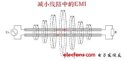
Electromagnetic interference EMI The interference signals generated by electronic equipment are transmitted through wires or common power lines, and mutual interference is called conducted interference. Conducted interference has caused confusion for many electronic engineers. How to solve conducted interference? Find the right method, you will find that the conduction interference is very easy to solve, as long as the number of EMC filters in the power input circuit is increased, and the parameters of each filter are adjusted appropriately, basically meet the requirements. The eight countermeasures explained below To solve the problem of dealing with conducted interference. Countermeasure 1: Minimize the effective area of ​​each loop Figure 1 Conducted interference from loop current Conducted interference is divided into differential mode interference DI and common mode interference CI. Let's first look at how conducted interference is generated. As shown in Figure 1, the loop current produces conducted interference. There are several loop currents in it. We can think of each loop as an induction coil, or the primary and secondary of the transformer coil. When there is current flowing in one loop, the induced electromotive force will be generated in the other loop. , causing interference. The most effective way to reduce interference is to minimize the effective area of ​​each loop. Countermeasure 2: Shielding and reducing the area of ​​each current loop and the area and length of the live conductor As shown in Fig. 2, e1, e2, e3, and e4 are differential mode interference signals generated by the magnetic field to the loop; e5, e6, e7, and e8 are common mode interference signals induced by the magnetic field to the ground loop. One end of the common mode signal is the entire circuit board, and the other end is the earth. The common end of the circuit board cannot be counted as ground. Do not connect the common end to the outer casing. Unless the casing is connected to the ground, the common end and the outer casing will increase the effective area of ​​the radiating antenna, and the common mode radiation interference will be more serious. . One way to reduce radiated interference is to shield, the other is to reduce the area of ​​each current loop (magnetic field interference), and the area and length of the live conductor (electric field interference). Countermeasure 3: Magnetically shield the transformer and minimize the effective area of ​​each current loop As shown in Figure 3, among all electromagnetic induction disturbances, the interference caused by the leakage inductance of the transformer is the most serious. If the leakage inductance of the transformer is regarded as the primary of the transformer induction coil, the other circuits can be regarded as the secondary of the transformer. Therefore, in the circuit around the transformer, an interference signal is induced. The method of reducing interference is to magnetically shield the transformer on the one hand and to minimize the effective area of ​​each current loop on the other hand. Countermeasure 4: Shield the transformer with copper foil As shown in Figure 4, the shielding of the transformer is mainly to reduce the leakage inductance of the transformer and cause electromagnetic induction interference to the surrounding circuits and external electromagnetic interference. In principle, the non-magnetic material does not directly shield the leakage flux, but the copper foil is a good conductor. When the alternating leakage flux passes through the copper foil, eddy current is generated, and the magnetic field direction generated by the eddy current Just in the opposite direction of the leakage flux, part of the leakage flux can be cancelled, so the copper foil can also shield the magnetic flux. Countermeasure 5: Using two-wire transmission and impedance matching Figure 5 Reduce EMI in the line As shown in Figure 5, if two adjacent wires have the same magnitude of current and opposite current directions, the magnetic lines of force they generate can cancel each other out. For circuits with relatively serious interference or relatively easy to be interfered with, try to use two-wire transmission signals. Do not use public ground to transmit signals. The smaller the common ground current, the smaller the interference. When the length of the wire is equal to or greater than a quarter wavelength, the line transmitting the signal must consider impedance matching. The unmatched transmission line will generate standing waves and generate strong radiation interference to the surrounding circuits. Bluetooth speaker,Portable bluetooth speaker, wireless protable outdoor speaker SHENZHEN YINZHIGUAN DIGITAL TECHNOLOGY CO.,LTD , http://www.yzgmusiccrown.com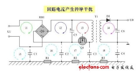
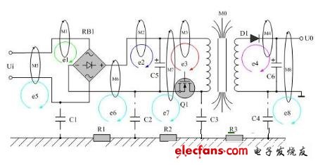
Shielding, reducing the area of ​​each current loop and the area and length of the live conductor 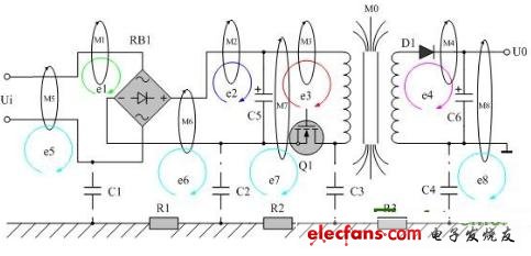
Figure 3: Electromagnetic induction generated by the leakage flux of the transformer 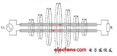
Figure 4 Reduce EMI in the line