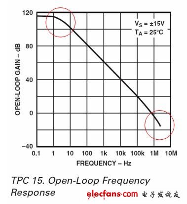
For engineers, the current source is an indispensable instrument, and many people want to make a common current source. The application of the open source kit is just a set of PCB, components, programs and other complete sets of products. Participants only need to The kit's things are soldered well, and debugging can be done. How much technical content can be used here, and how much technology can we learn from it? This article is only from the principle of telling, to guide everyone to do the current source that individual can control. This article is mainly to design the content of the simulation part, and basically does not involve the single-chip microcomputer, I hope that friends can learn from the knowledge. Last time I talked about "Current Source Design Small Tips (2): How to Solve the Op Amance Oscillation Problem", and today I will look at other parts of the study. The idea is roughly the same: 1. The reason for choosing a power MOSFET is based on two considerations. First of all, the power MOSFET is not very slow, and the steady source is not required to be fast. Secondly, the cost and power capacity. The first use of the power MOSFET is the safe working area. The power supply should be used in response to various operations of the user. Many of them are in violation of the regulations, but the user can only ask for education, so the safe working area will be selected. I have a lot of money. In fact, there are few MOSFETs that are more suitable than the 520/530 in terms of price, performance, and maximum power that this current source can produce. For steady applications, this current source architecture is not a fatal problem and is a typical approach. Frequency compensation is inevitable in all linear power supplies, and the time spent on compensation during the development process is basically the same, but the experience is different. The compensation is very simple, and the theory is long and cumbersome. The reason why we have spent a lot of effort is to understand that the oscillation is analyzable and controllable, and it is not necessary to be in a state of flux. 2. The oscillation in the 1M bandwidth is sometimes more terrible for the load than the high-frequency oscillation. For the linear power supply, 1M is just in the processing frequency band of the system (and high and no vibration), so the oscillation amplitude may be extremely impressive. 47th floor] yan_jian should be very deep. It was once oscillated by 10k, 36Vpp, and it feels similar to 220V. As for the superposition processing, as long as it is not DC, the Laplace transform should not be a problem. pH is indeed a risk of potential oscillation under any circumstances, but in order to distinguish the difference between po and pH, the order of po is easy to find and is in the front. At this time, pH is a secondary contradiction. . In the actual circuit, Cgs may reach 10000pF (30N50), po is not 800k, it is likely to have a role when gm is small. Moreover, the treatment of po and pH is very different. One kind of compensation is difficult to handle at the same time, and different compensation methods are used. After all, it is not a theoretical lesson. It is basically a reproduction of the debugging process, and the analysis process is more focused on hands-on. Super beta tubes are common in bipolar op amps 10 years ago, usually beta 3,000. If beta=1200, the normal Darlington structure can be reached. Naturally, this is a pure bipolar planar process, so there is certainly no CMOS. BiCMOS should not be used due to MOS characteristics. The analysis of the transistor level has been put down for a long time, and many parameters can't be remembered. It is really a headache to pick it up. If there is an error, please correct me. Hehe, when I saw Dabu, I remembered a fever, and there was a big box of supplements that I couldn’t use. Only used 2 cents, 7 common components. Commercial linear power supplies are used more. The compensation components in the Agilent 364x are not completely counted at least 20 at a glance. There are more than a dozen of the products on the slab that I have seen in the product. There are only a dozen between the output of the op amp and the gate of the MOSFET. The slope before pL is 0. After pL, the slope is -20dB/DEC (-6dB/octave). After po, the slope is -40dB/DEC (-12dB/octave). After pH, the slope is -60dB/ DEC (-18dB/octave). The pole reduces the slope of the subsequent amplitude frequency response curve by 20 dB/DEC. The zero point increases the slope of the amplitude band response curve by 20 dB/DEC. Halo, and quickly checked the book, it should not be wrong, huh, huh. PS: pL/pH differs by 6 DECs. The first two DEC phases of the pole start to deflect. When the pole reaches the pole, it is -45. After two DECs, it reaches -90. Before compensating, the phase at po is exactly -135, then exceeds -135, making the phase margin less than 45, and the system oscillates. Meet the stability criteria.
The FirstPower Long Life Battery is desgined for apllcation as General Purpose and long life. The series focus on improving trickle life that base on Standard series.
We welcome orders with "FirstPower" brand; We are also flexible to accept orders on OEM basis. Contact us now! Your partnership with FirstPower will prove worthy of it.
Long Life Battery Long Life Battery,Gps Tracker Long Life Battery,Long Life Electric Scooter Battery Firstpower Tech. Co., Ltd. , https://www.firstpowersales.com