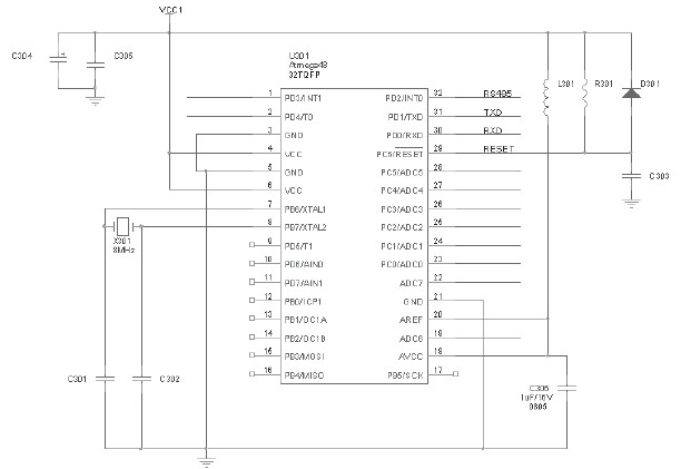
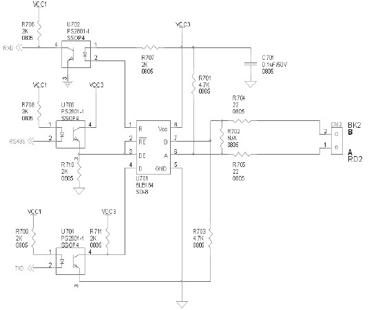
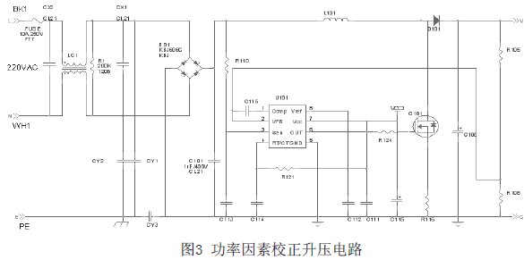
introduction Electronic ballasts are new energy-saving products that not only can drive some lighting fixtures, but also can be combined with some UV lamps, which have a great effect on air purification and water purification. At present, the world is vigorously promoting environmental protection, and electronic ballasts indirectly provide the driving force for environmental protection. AVR MCU is a cost-effective single-chip microcomputer. It is very suitable to use the MCU to dim and time sample the electronic ballast. First, the AVR MCU itself is stable and has strong anti-interference ability, followed by its own Harvard. The structure makes the running speed faster, the data readback time is faster, and real-time online control can be realized. 1 AVR microcontroller introduction 1.1 Features of AVR Microcontroller Compared with the previous 8-bit single-chip microcomputer, the AVR microcontroller adopts the Harvard structure, that is, the program bus and the data bus are separated, and adopts a two-stage pipeline with a high-speed operation processing capability of 1 MIPS/MHz. On-chip integration of multiple frequency RC oscillator, power-on automatic reset, watchdog, start delay and other functional modules, the peripheral circuit is simple, the system is more stable and reliable. Most AVRs are rich in resources: with E2PROM, PWM, RTC, SPI, UART, TWI, ISP, AD, Analog Comparator, WDT and other unit modules. 1.2 AVR microcontroller PWM function The AVR microcontroller's timer is powerful. Take the Atmega48 as an example. It has two 8-bit timers and a 16-bit timer, all with hardware PWM function. Each timer has two output compare units to make the PWM simpler. AVR timer PWM wave divided into 5 types of work (1) Normal mode. The simplest mode of operation in which the counters are constantly accumulating. After counting the maximum value (MAX=0xFFFF), the counter simply returns to the minimum value of 0x0000 and restarts due to the value overflow. (2) CTC mode. a. A square wave signal for outputting a 50% duty cycle; b. for generating an accurate continuous timing signal. (3) Fast PWM mode. Used to output high frequency PWM signals (double the frequency higher than the double ramp). 1.3 AVR microcontroller serial communication function AVR MCUs effectively support C high-level languages. Serial port reception can use interrupt mode or query mode. AVR serial port is full-duplex operation (independent serial receive and transmit registers), support asynchronous or synchronous operation, support 5,6 7, 7, 8 or 9 data bits and 1 or 2 stop bits. The hardware supports parity operation. There are three independent interrupt sources, including UART receive completion interrupt, transmit completion interrupt, and register empty interrupt. When receiving data, you can also use the way of query, which itself uses interrupt. 2 electronic ballast 2.1 Advantages of electronic ballasts (1) Energy saving. The power loss of the electronic ballast is only about 40% of that of the magnetic ballast, and the luminous efficiency of the fluorescent lamp is increased by 20% at a high frequency of about 30 kHz, the operating current is only about 40% of the inductance, and it can be at a low temperature. Start and work at low pressure. (2) No strobe. When the lamp is working at around 30 kHz, the light is stable, and the human eye does not feel "strobe" to protect the eyesight. (3) No noise. Conducive to working and learning in a quiet environment. (4) High power factor. The reactive power loss is reduced, the effective utilization of the power supply equipment capacity is improved, and the line loss is reduced. (5) It has its own protection functions, such as no lamp protection and overvoltage protection, which enhances the reliability of electronic ballasts. 2.2 Hardware circuit design of electronic ballast (1) Figure 1 shows the control circuit of the AVR microcontroller. The chip uses Atmega48. The pins PD0 and PD1 of the MCU are used as the receiving and transmitting ends of RS485 . PD2 is connected to the output of RS485. (2) Figure 2 is the communication circuit of RS485. The receiving end and the input end are respectively connected with an optocoupler to isolate the receiving and transmitting signals. Since the input and output of the optocoupler are isolated from each other, it has good electrical insulation capability. And anti-interference ability. Moreover, since the input end of the optocoupler belongs to a low-resistance component of current type operation, it has strong common mode suppression capability. The 6LB184 is a differential transceiver with transient voltage suppression, which is more resistant to noise. (3) Figure 3 shows the input EMI filter and PFC boost circuit. LC1 and CY1, CY2 are used to filter common mode noise, and CX1 and CX2 are used to filter differential mode noise. UC2843 is a fixed frequency pulse width modulator, and Q101 constitutes a boost circuit. The power factor correction circuit is used to increase the conduction angle of the rectifier, and at the same time, the waveform of the input AC current is positively selected and is in the same direction as the voltage waveform.