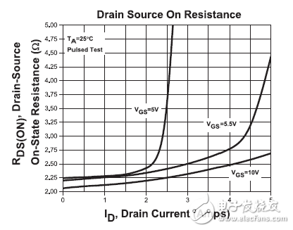
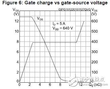
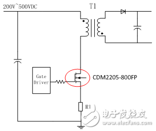
In today's Switching Power Supply equipment, the characteristics of the MOS tube, parasitic parameters and heat dissipation conditions will have a significant impact on the performance of the MOS tube. Therefore, an in-depth understanding of the working principle and key parameters of the power MOSFET is critical to the power supply design engineer. At present, the two loss factors that affect the efficiency of the switching power supply are: conduction loss and switching loss. The following two types of loss are specifically analyzed. Conduction loss The conduction loss is specifically generated by the on-resistance Rds of the MOS transistor, and Rds is related to the gate driving voltage Vgs and the current flowing through the MOS transistor. If you want to design a more efficient, smaller power supply, you must reduce the on-resistance sufficiently. Figure 1 shows the graph of the on-resistance Rds, Vgs and Id: Figure 1: Graph of on-resistance Rds vs. Vgs and Id Switching loss The gate charge Qg is the main cause of switching loss. The gate charge is the energy required for the gate charge and discharge of the MOS transistor. The MOSFET with the same current and voltage specifications has a relatively large gate charge, which means that more energy is lost during the MOS switch. Therefore, in order to reduce the switching loss of the MOS tube as much as possible, the engineer needs to select the MOS tube with the lower Qg of the same specification as the main power switch tube in the power supply design process. Figure 2 shows the graph of gate charge Qg and Vgs: Figure 2: Graph of gate charge Qg and Vgs MOS tube selection For switching power supply applications, Central Semiconductor has introduced a range of low-power Rds and Qg power MOSFETs. The representative model is CDM2205-800FP, which has the following performance advantages: • Maximum withstand voltage is 800V • Maximum continuous current 5A • On-resistance as low as 2.2Ω • Gate charge Qg is only 17.4nC Figure 3 shows the application of the CDM2205-800FP in a flyback switching power supply. In the power supply design device selection, first determine the maximum voltage that the device can withstand according to the input voltage of the power supply. The higher the rated voltage, the higher the cost of the device. It is then necessary to determine the rated current of the MOS tube, which should be the maximum current that the load can withstand in all cases. Ensure that the selected MOS transistor is capable of withstanding continuous current and pulse spikes. Figure 3: Application of CDM2205-800FP in flyback switching power supply Switching Power Supply ZhenHuan' series of ac/dc switching power supplies output power ranging from 5 W to 200 W is available in a variety of wall plug-in and desktop adapter configurations to meet your needs. From our low power international wall plug adapters to our high power desktop ac-dc power adapters, we ensure that the majority of our external switching power supplies not only comply with the current energy efficiency Level VI standards, but also meet global safety certifications. RoHS Switching Adapter,Switch Mode Power Supply,100-240v Switching Power Supply,Switched Mode Power Supplies,Power Adapter Switches Shenzhenshi Zhenhuan Electronic Co Ltd , https://www.szzhpower.com