High Frequency Power Supply Transformer EE 30 abb transformer,RM6 frequency transformer,ETD44 power transformer,EFD20 high frequency transformer IHUA INDUSTRIES CO.,LTD. , https://www.ihua-coil.com
Overview Application Note 4303: "The Impact of Cable Loss on Automatic Test Equipment" discusses the signal attenuation mechanism of high-loss cables. The loss mainly comes from two aspects: skin effect and dielectric loss. Equipment manufacturers, such as those that provide automatic test equipment (ATE), mostly use high-loss cables in order to reduce the overall system cost. With the increase of system data transmission rate, the impact of these cables on system performance has far offset their low cost advantages. Thankfully, electronic circuits can be used to compensate for cable losses.
Possible solutions to cable loss One of the ways to solve the high cable loss is to choose high-quality, expensive cables, which have the least negative impact on system performance. But only some special high-end systems, such as military equipment, can accept this high-quality cable. The high cost severely restricts the use of this type of cable. In addition, the cable diameter also limits the number of cables that can be used in the system, and even high-quality cables can cause significant losses.
Another solution is to design an appropriate electronic circuit, not only for driving the cable, but also to balance the cable loss. This solution uses small-sized lead electronics (PE) to drive the cable, allowing the use of thin, low-cost, high-loss cables. The device also compensates for losses caused by PCB leads, relays, and connectors. In addition, this solution makes the system performance close to the performance index that PE can provide, without considering the cable loss.
The last solution is to combine the above two methods, but the PE solution is the most practical option, which is also the focus of this article.
Solving cable loss electronically Figures 1 and 2 describe cable loss, which causes the edges of the waveform to become smooth, or to "wear" the final signal. It is the edges of these "smooth" signals that reduce the effective bandwidth of the system. The bandwidth loss is due to the cable rather than PE. In order to optimize system performance, it is necessary to restore effective system bandwidth. 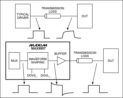
Figure 1. Basic principle of driver cable loss correction 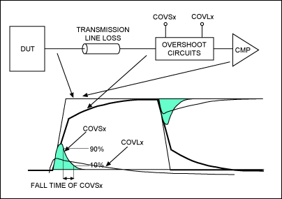
Figure 2. Compensator channel cable loss compensation
In order to correct the signal "wear" and restore the bandwidth, a method must be found to restore the waveform edge to a steep, noise-free square wave directly from the driver. This correction must be achieved using the PE of the drive cable. Figure 1 contains an additional circuit module "waveform shaping", which can effectively repair the edge of the signal by increasing the controllable overshoot amplitude. Edge repair is not achieved by a simple overshoot circuit. The simple overshoot circuit will negatively affect the edge and cause amplitude fluctuations. The amount of overshoot depends on the specific overshoot added. These undesirable effects can cause errors such as timing and signal offset, and these errors vary with changes in frequency and amplitude.
Figure 2 shows the more detailed Maxim product's method for correcting cable loss. Figure 1 shows the waveform correction of the entire drive circuit of the PE IC from the cable to the device under test (DUT). Figure 2 lists a similar correction situation, from the DUT through the cable to the PE comparator. Both driver and comparator paths need to be revised.
The cable loss compensation circuit adds two first-order time constant attenuation peak signals to the signal. The DOVSx input voltage controls the peak level with a shorter duration to compensate for overshoot voltage; the DOVLx input voltage controls the peak with a longer duration to compensate for the overshoot voltage. Overshoot signals of shorter or longer duration are limited to 10% overshoot. The two peak signals have fixed decay time constants. The time constant of the DOVSx signal is 77ps, and the time constant of the DOVLx compensation is 1.5ns. As shown in Figure 2, COVSx and COVLx serve similar functions in the comparator channel.
The MAX9957 dual-channel 2000Mbps driver and the MAX9955 dual-channel 2000Mbps comparator / terminator use dual time constants. As shown in Figures 1 and 2, the two time constants can be adjusted separately.
The MAX9979 dual-channel 1100Mbps driver / PMU has a level setting calibration DAC and uses a single control architecture (shown in Table 1 and Figure 3). This scheme also uses dual time constants, but combines the dual time constants into a 3-bit DAC.
Table 1. MAX9979 cable attenuation compensation control Serial Interface Bits Droop CompensaTIon (%) CDRP2_ CDRP1_ CDRP0_ 0 0 0 0.0 0 0 1 1.5 0 1 0 3.0 0 1 1 4.5 1 0 0 6.0 1 0 1 7.5 1 1 0 9.0 1 1 1 10.5 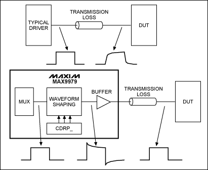
Figure 3. MAX9979 cable compensation
MAX9979 performance test under different cables The MAX9979 is a dual-channel PE that integrates driver / comparator / load (DCL), PMU, and level setting calibration. Each channel consumes 1.1W of power, optimized for 1Gbps, 3V signals, and terminated with 50Ω.
Figures 4 to 9 provide a set of test data for MAX9979. The test platform is similar to Figure 3. These test data are obtained under the following conditions: MAX9979 is configured at VDH = 3V, VDL = 0V, and provides a 3V signal drive for a 50Ω load. The corresponding cables are shown in the figure.
It can be seen from the test results in Figures 4 to 9 that the compensation cable has obvious advantages compared to the uncompensated cable. Figures 8 to 9 are close to the actual test results of the high-speed test device. You can clearly see the level jump rate or system bandwidth, which is almost 50% lower. These losses are the attenuation caused by the cable. In some cases the results may be worse, because the cables used by ATE are more lossy than the cables used in the test. In addition, these tests also include the loss of PCB traces, relays, and connectors in the signal path. The PE cable compensation in Maxim's ATE product line can compensate for the loss of all signal channels. 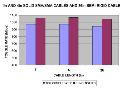
Figure 4. Conversion rates before and after compensation, using solid-state and semi-rigid SMA cables 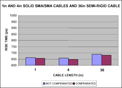
Figure 5. Rise time before and after compensation, using solid-state and semi-rigid SMA cables 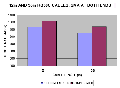
Figure 6. Conversion rate before and after compensation, using RG58C cable 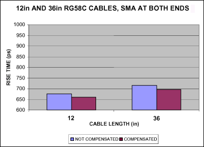
Figure 7. Rise time before and after compensation, using RG58C cable 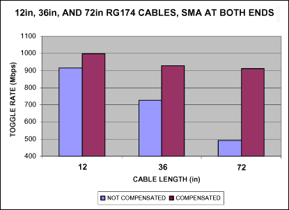
Figure 8. Conversion rate before and after compensation, using RG174 cable 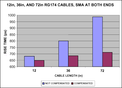
Figure 9. Rise time before and after compensation, using RG174 cable
Further analysis of the data in Figures 4 to 9 shows that the reduction in level conversion rate and the extended rise time are the keys to cable loss, and this phenomenon is easier to see from channels without compensation. The loss depends on the length and quality of the cable used. In actual applications, the loss caused by the cable itself may exceed 50%.
Note: The price of solid SMA cable used in the test is $ 130 / ft, the price of semi-rigid cable is $ 30 / ft, and the price of RG58 and RG174 cables is $ 5 / ft. The expensive cable has good performance, and the transmission length can even reach 36 inches. But these expensive cables also need compensation to support the highest data rates and minimum rise times. 12-inch, especially 36-inch RG58 cable, even under compensation, the level conversion rate is significantly reduced, and the rise time is longer. Uncompensated cables have greater losses. As can be seen from Figure 8 and Figure 9, when there is no compensation, a long high-loss cable will greatly reduce system performance. Compensating these cables can restore the signal bandwidth or increase the level conversion rate, reaching more than 90% of the driver's performance indicators. Without a cable compensation system, if the PE driver can support 1000Mpbs or higher, the loss caused by cable loss, relays, connectors and PCB leads may be as high as 50%. On the contrary, using a PE system with cable loss compensation, the system performance can reach 90% of the index that the PE device itself can provide. The PE compensation must be adjustable. If the PE only uses a simple overshoot circuit, it cannot compensate for a specific length of cable, because the edge and ripple will change with frequency and amplitude, thereby introducing timing errors. Figure 10 and Figure 11 are the actual measurement results of 6 feet and 3 feet RG174 cable. The data of Figures 8 and 9 are extracted directly from these results. The output results include uncompensated waveforms, fully compensated waveforms, and 1-bit overcompensated waveforms. 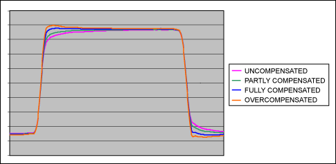
Figure 10. 6-foot RG174 cable output waveform, the four waveforms are: no compensation, partial compensation, full compensation and over-compensation (please refer to the relevant data in Figure 8 and Figure 9). 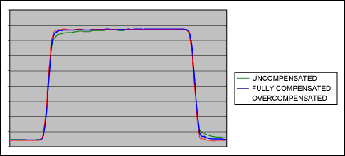
Figure 11. The output waveform of the 3-foot RG174 cable. The three waveforms are: no compensation, full compensation and over compensation (please refer to the relevant data in Figure 8 and Figure 9).
The above waveforms show that the strict PE cable compensation design can maintain the true signal edge and even reduce the amplitude fluctuations, thereby maintaining the correct transient level and making the system obtain the best performance at any frequency and amplitude.
Summary of test results The test results shown in Figures 4 to 11 confirm the above theoretical analysis and related discussions. The quality of the cables used in the test is better than the cables used by ATE equipment. Obviously, without the cable compensation circuit, the system will not reach the same performance index as PE. Similarly, designing cable compensation in PE can achieve almost 100% performance indicators, very close to the highest rate that PE can support.
Design a cable compensation circuit in the electronic driver to enable the system to use low-cost, high-loss cables while ensuring overall performance. Adding this compensation function to the driver will increase the cost of each pin. However, the improved performance and the use of low-cost cables can undoubtedly compensate for the increase in pin costs and ultimately reduce the overall cost.
Cable loss
Abstract: This application note describes a cable loss compensation method that allows test equipment manufacturers to use high-loss cables to reduce costs without sacrificing product performance.