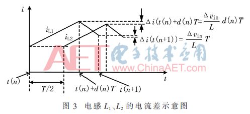
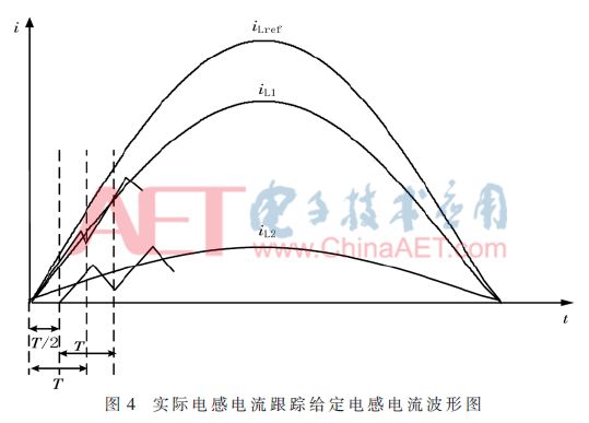
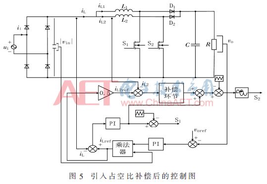
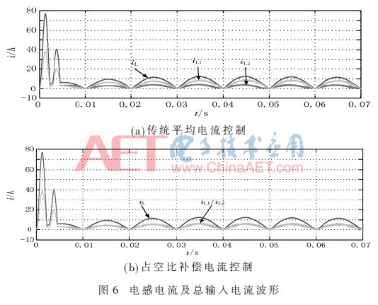
Summary: Aiming at the problem that the current stress of the switch tube in a branch is increased due to the uneven current of each branch of the two-phase interleaved Boost PFC converter in the continuous conduction mode (Continue Conduction Mode, CCM) of the inductor current of the power factor correction converter, adopt Duty cycle compensation current control strategy. Based on the average current control, this control strategy adds a compensation loop inside the parallel branch, and compensates for the duty cycle according to the deviation of each phase current from a given input current of 1/2, and realizes the equalization of the two parallel branches. Flow, and finally achieve the purpose of reducing the current stress of the switch tube. Finally, a simulation circuit is established. Through simulation analysis, it can be seen that when this control strategy is not adopted, the currents of the two branches are 5 A and 2.2 A respectively, and the peak current of the 5 A branch MOS tube is 9.2 A; After compensating the current control strategy, the currents of the two branches are both 3.6 A, and the peak currents of the two MOS transistors are both 6.8 A. The current sharing effect is obvious, and the current stress of the switching tubes is reduced, which verifies that the duty cycle compensation current control is staggered in parallel The feasibility of CCM Boost PFC converter. ■0 Preface The rapid development of my country's electric vehicle industry, a large number of electric vehicle charging behaviors bring a lot of harmonics to the grid [1-2]. In the literature [3], Boost circuit is used as the rear stage of the rectifier circuit to realize the power factor correction (PFC) and reduce the harmonics of the power grid. With the development of PFC technology, new PFC topologies are constantly being proposed, such as voltage doubler PFC, bridgeless PFC, interleaved parallel Boost PFC, etc. [4-5]. Among them, the staggered parallel Boost PFC system not only has all the advantages of the parallel system, but also reduces the input current ripple and reduces the current stress of the switch tube. In high-power places, the interleaved parallel Boost PFC converter working in the continuous conduction mode (Continue Conduction Mode, CCM) [6] of the inductor current is usually used. Based on the topology of the existing PFC converter, the following control methods have been proposed: peak current control, average current control, single-cycle control, etc. [7-8]. Among them, the average current control has better dynamic and static characteristics than other control methods. Secondly, the current sharing problem should also be considered in the parallel system. If the currents of the two branches of the parallel system are not balanced, the current stress borne by the switch tube of a branch will inevitably increase, which will increase the probability of damage to the switch tube [9]. Aiming at the problem of increased switch tube current stress caused by the uneven current of the two branches in the average current control interleaved parallel CCM Boost PFC converter, this paper analyzes the principle of uneven current and adopts the duty cycle compensation current control strategy to achieve The current sharing control of the parallel two-phase Boost circuit solves the above-mentioned problems. 1 Working principle of interleaved parallel CCM Boost PFC converter The schematic diagram of the interleaved parallel CCM Boost PFC converter is shown in Figure 1 (a), and the steady-state timing waveform is shown in Figure 1 (b). As shown in Figure 1(b), the interleaved parallel CCM Boost PFC converter is composed of two identical Boost PFC converters in parallel, and the drive signals of a single switch tube S1 and S2 have a phase difference of 180°, as shown in Figure 1(b) , The drive signal of the switching tube S2 lags behind the switching tube S1 by 180°. The current waveforms of the inductor L1 and the inductor L2 branch are the same, and the phase difference is 180°. Therefore, the currents of the two branches are interleaved and connected in parallel to eliminate part of the current ripple. , So that the ripple of the total current i is reduced, and the frequency becomes twice as much as before. 2 The uneven current problem of the average current control interleaved parallel CCM Boost PFC converter 2.1 Single CCM Boost PFC circuit current tracking analysis A single CCM Boost PFC circuit is shown in Figure 2. In the circuit shown in Figure 2, the inductor L works in continuous mode, and the duty cycle expression is [10]: According to the principle of the average current control strategy [11], combined with the analysis of equations (2), (8), and (9), we can see that: each switching cycle, the duty cycle is different, t(n)+d(n)T time The inductor current at t(n+1) is also different (varies with the input voltage vin(t(n)) and the duty cycle d(n)), so the inductor current has good current tracking characteristics. 2.2 The uneven current principle of the interleaved parallel CCM Boost PFC circuit As shown in Figure 1, in the interleaved Boost PFC circuit in parallel, the inductance L1 and the inductance L2 are equal in size to L. For the inductance L1, it can be obtained by formula (8) and formula (9): Analyzing equations (14) and (15), we can get: there will be a current difference between the inductance L1 and the inductance L2 at the time t(n)+d(n)T and t(n+1), as shown in the figure 3 shown. The actual inductor current iL1 and iL2 track the waveform of the given input current iLref as shown in Figure 4, the uneven current phenomenon is obvious. 3 Duty cycle compensation control loop Based on the above analysis, the conduction delay of the switch tube in the interleaved control causes the iL2 current to not track the given current well, and uneven current occurs. In order to ensure that the inductor current iL2 can track the given current well, an improvement is made on the basis of the traditional average current control shown in Figure 1(a), and the duty cycle compensation loop is added to the traditional current inner loop to compensate the current sharing duty. By comparison, both the inductor current iL1 and the inductor current iL2 can track the given current well to achieve the purpose of current sharing. The control diagram after introducing the duty cycle compensation control loop is shown in Figure 5. 3.1 Principle of the duty cycle compensation control loop In order to realize the current sharing of the interleaved parallel CCM Boost PFC converter with two modules connected in parallel, it is considered that only two modules are connected in parallel. Therefore, when designing the duty cycle compensation control loop, it is only necessary to add the duty cycle compensation control loop to one of the branches. When the inductor current of one branch reaches 1/2 of the total current after compensation by the current sharing duty cycle, the current of the other branch must also be 1/2 of the total current, achieving the purpose of current sharing between the two branches. Based on the previous analysis of the uneven current principle, the switch-on delay in the interleaved control produces a small input voltage increment Δvin, which causes the inductor current iL2 to not track the given current well, and the currents of the two branches form a current deviation. Therefore, a duty cycle compensation link is added to the current loop of the current deviation source branch (inductor L2 branch) to compensate the current sharing duty cycle to the control duty cycle of the current inner loop output of the average current control, so that the inductor The current iL2 is 1/2 of the total current, so the inductor current iL1 is also 1/2 of the total current, realizing the current sharing of the two branches in parallel. 3.2 The design of the compensation link algorithm According to the ratio of the difference ΔiL2 between the given value of the branch current 1/2 (iLref) of the inductor L2 and the actual value iL2 to the given value of the branch current 1/2 (iLref), the current deviation degree of the inductor L2 branch is obtained: The DC input voltage vin of the interleaved parallel CCM Boost PFC converter is the sine half-wave of the output voltage of the rectifier bridge, and its range is between zero and the peak voltage vpk. When vin is near zero, the control duty cycle is the largest, and when vin is the peak value , The control duty cycle is the smallest. Therefore, in the duty cycle compensation control loop, the maximum current sharing duty cycle that can be used for compensation is the maximum control duty cycle: 4 Simulation verification Based on MATLAB/Simulink simulation software, the interleaved parallel CCM Boost PFC converter with duty cycle compensation current control strategy is simulated. The main circuit parameters are: grid voltage 220 V, 50 Hz; output voltage vo=400 V; inductance L1=L2=800 μH; capacitance C=400 μF; switching frequency is 50 kHz; current sharing duty cycle that can be used for compensation The maximum value is the maximum value of the control duty cycle: 0.78. Under the two control strategies, the inductor current, the total input current waveform, and the switching tube current waveform are shown in Figure 6 and Figure 7, respectively. The simulation results show that compared with the traditional average current control, the current control with duty cycle compensation has an obvious current sharing effect, and the current stress of the switch tube is significantly reduced. 5 Conclusion Due to the uneven current flow of the two parallel Boost branches caused by the interleaving control, this article improves on the traditional average current control strategy. By analyzing the average current control, the interleaved parallel CCM Boost PFC converter adopts duty cycle compensation current control. Strategy, adding the duty cycle compensation control loop, let the current-sharing duty cycle compensate the output duty cycle of the current inner loop controlled by the average current, and analyze the compensation principle and algorithm, and finally carry out simulation verification. The analysis in this paper shows that the interleaved parallel CCM Boost PFC converter with duty cycle compensation current control not only has all the advantages of the traditional average current control strategy, but also realizes the current sharing of the two parallel Boost branches and avoids some problems caused by uneven current. The problem of excessive current stress on a branch switch tube. POWER-D & COMBO-D D-SUB CONNECTORS
Industry standard terminations types, solder cup, PCB contacts in straight and angled pin configurations. Crimp types and wire wrap contacts.
Combo Power D-sub Connectors,RJ45 3U Gold,Gold Flash Plated,8P8C with Shield,Shield with EMI ShenZhen Antenk Electronics Co,Ltd , https://www.atkconnectors.com


The ANTENK POWER-D & Combo-D mixed contact d-sub connectors are designed for rugged / robust applications where both power & signal are required from a single connection. Featuring [Solid-Pin" machined contacts, these connectors offer high reliability performance for the most challenging design applications.
Combination D-SUB Connectors provide the ideal solution for applications to require power, signal and coaxial connections within one connector. This series of connectors achieves space saving on PCB`s and I O designs.
Within this product family are various pin out configurations possible. Almost endless selections can be created mixing power, signal and coaxial contacts.
Power contacts from 10 amp to 40 amp current handling. Signal contacts in various styles complete the product offering.
â– Space savings on the PCB
â– Different wire terminations are possible in a single connector
â– Cost savings - mixed layout
â– Insertable and removable coaxial, power, high voltage and signal contacts
â– Precision machined contacts
â– Various quality classes are available
â– Wide product range
A wide range of standard pin configurations fully loaded with signal contacts are available. Specially configured contacts with power, coaxial and signal contacts can be constructed.
D sub power connector Applications
Communications
Base Stations
Switching
Transmission
Asymmetric Digital Subscriber Line (ADSL)
Data
Desktops/ Laptops
UPS, Storage systems
Routers, Servers
Printers, Copiers
Consumers
Consumer Electronics
Set-top-boxes
Energy meters
Industrial & Instrumentation
Robotics
Control Drives
Power Supplies
Medical Instruments
Test Equipments
POS & Handheld terminals
Renewable Energy
Surveillance Camera
Office Automation
Parking Meters
Gaming Machines