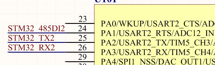
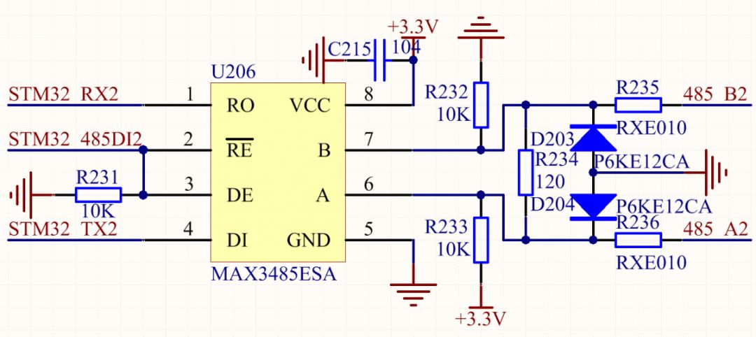
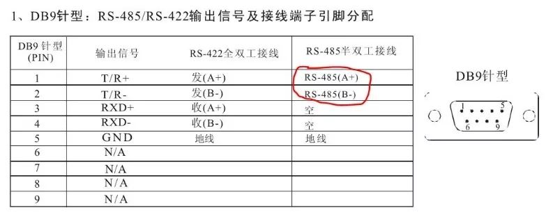
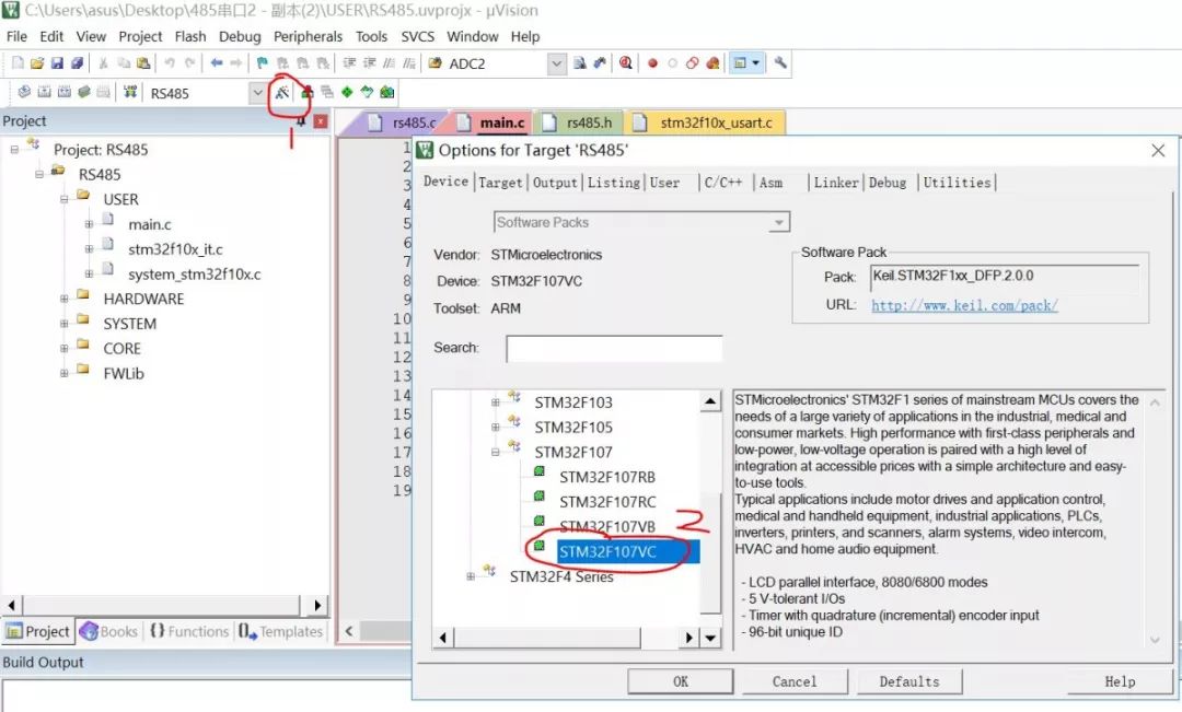
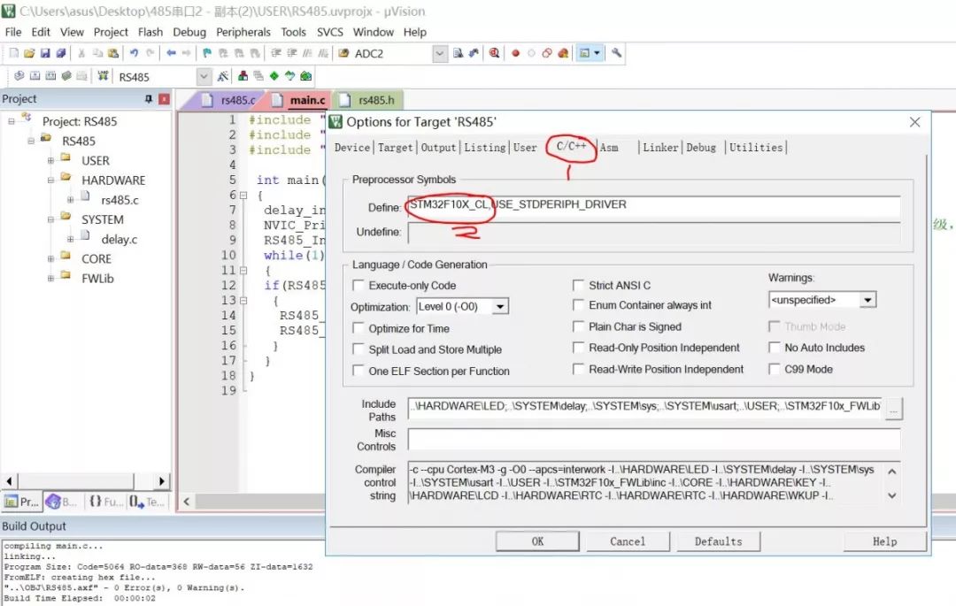
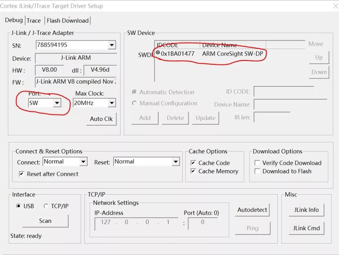
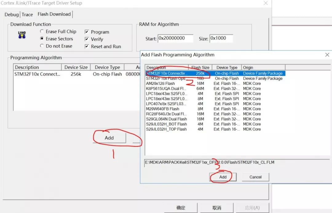
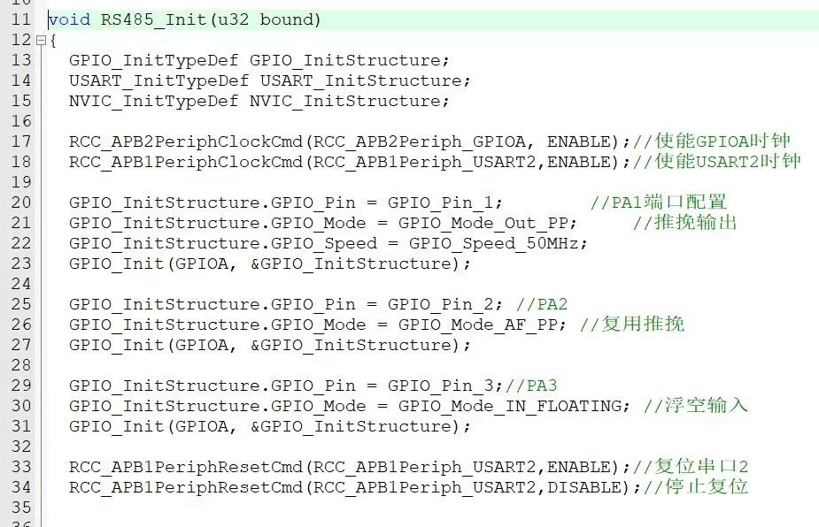
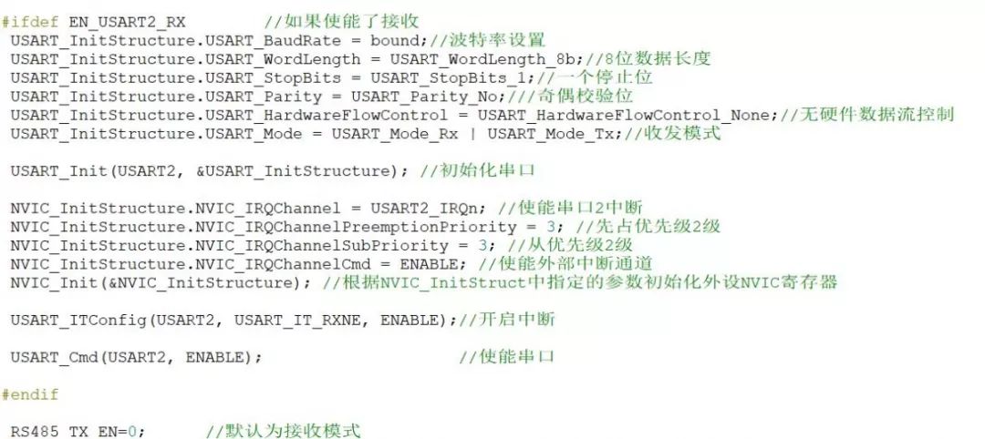
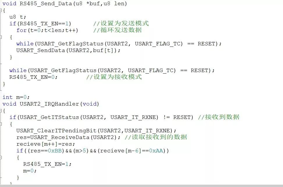
(This article is the original manuscript of the electronic enthusiast network user Fengfu Catkins) As we all know, serial data communication methods include simplex mode, half-duplex mode and full-duplex mode. Simplex mode: only supports data transmission in one direction; half-duplex mode: allows data to be transmitted in both directions, but only in one direction at a time; full-duplex mode: in both directions at the same time Transmission, which is the combination of two simplex communications, requires both the sending device and the receiving device to have independent receiving and sending capabilities at the same time. For example, our common RS232, RS485, and RS422 serial communication methods, among which RS232 is full-duplex, RS485 is half-duplex, and RS422 is full-duplex. Of course, two half-duplex 485 can form a 422 communication method. Let's talk about today's key RS485 communication methods. If you understand 485 communication, you will have a basic understanding of 422 communication. Let’s first introduce the electrical characteristics of RS485. RS485 adopts differential transmission. The logic “1†is represented by the voltage difference between the two lines as +(2~6)V; the logic “0†is represented by the voltage difference between the two lines as -( 2~6) V represents. The interface signal level is lower than that of RS232, which is not easy to damage the chip of the interface circuit, and the level is compatible with the TTL level, which can be easily connected with the TTL circuit. The transmission rate is high, the anti-interference ability is strong, and the communication distance can be greatly extended. For example, the transmission distance of RS232 is generally 30 meters, and the use of RS485 does not need to modify the program at all, and the communication distance can reach 1200 meters (9600bps). And RS485 generally supports a maximum of 32 nodes, realizing multi-node sending and receiving. The special 485 chip can realize more nodes to send and receive. Since RS485 communication is so excellent, let's start today's example. First of all, STM32F107VCT6 is selected in this example, as shown in Figure 1, and the one allocated to 485 communication in Figure 2 Pin, this time PA2 is used as the sending end of the microcontroller, PA3 is used as the receiving end of the microcontroller, and PA1 is used as the control end for receiving and sending. The A2 and B2 pins output on the board are respectively connected to the T/R+ and T/R- of DB9, here for different DB9 pins The location is different, the reader pays attention to distinguish. The hardware circuit is basically completed here. The following is the software debugging part, Step1, find the chip type F107VC in Device in the corresponding configuration. Of course, the selection of different chips must be correct. Step2, in the corresponding macro definition, change the circle to CL. Because the chip flash is 256K this time, it belongs to the small chip capacity. Step3, configure the jlink driver, select the four-wire SW mode, the four wires are 3.3v, SWDIO, SWCLK, GND. See the model in the circle that appears in SWDevice, and click Flash Download to see the interface shown below to see if the chip selection is 256k, instead of clicking Add, select the flash size of 256k, and then some columns are OK. Step4, the writing of the main function, of course, some operations such as new projects are omitted this time. If you don’t understand, you can give Baidu step instructions. The main function program is very simple, an interrupt configuration function, and a 485 initialization function. Of course, the 485 initialization function includes For many configurations, see below for details, and the delay function can be omitted this time. The main function is a send and receive enable switch (RS485_TX_EN) and a send function. Step5, define the 485 initialization function, pin configuration, here is PA2 output, PA3 input, PA1 is the enable bit, please refer to the above schematic diagram for details, and at the same time, in this function, the baud rate and serial port interrupt are performed. configuration. Step6, 485 sending function and interrupt function are defined. Since external interrupt is not used this time, but internal interrupt method is adopted, the received data is stored in the receive array in serial port 2 interrupt, and the packet header and The packet bits are 0xAA and 0xBB respectively, and the length of the transmitted data is set to 6. The data that does not meet the next three conditions cannot be sent by the serial debugging assistant. Of course, always pay attention to whether the enable bit (RS485_TX_EN) is 1 or 0, which is 1 means 485 transmission, 0 means 485 reception, because 485 is half-duplex, as mentioned earlier, it can only receive or transmit at a certain time. And define the corresponding functions and arrays as global in the header file. Step7, the last part of the test is the most stressful part. Adjust the configuration in the serial debugging assistant circle to the same form as the code configuration, and change the format of the sent data to a format with 4 bits in the middle of the packet header, AA, packet tail, and BB. Send, click send, you can receive this data in the serial port debugging assistant. Of course, if the packet header and packet bits are 0xAA, 0xBB, respectively, and the format of the sent data length is 6, it will not be received in the serial port assistant. Data, readers can try by themselves, the layout is limited, and there is not much explanation. Step8, I have little talent and knowledge. I am just exploring the single-chip microcomputer stage. It may not be perfect in many places. I hope that the big guys will criticize and correct me, and give me some advice. I would like to thank everyone in advance. Type C Hub 8 In 1,Best Buy Usb C Hub,Usb C Hub For Macbook Pro,8 in 1 Type-C Multifunction Docking Station, 8 in 1 USB-C Multiport Docking Station Shenzhen Konchang Electronic Technology Co.,Ltd , https://www.konchang.com