BestCap is a registered trademark of AVX Corp. Silicone Protective Sleeve,Silicone Sleeve For Glass Bottle,Silicone Water Bottle Sleeve,Bottle Silicone Sleeve Nantong Boxin Electronic Technology Co., Ltd. , https://www.bosencontrols.com
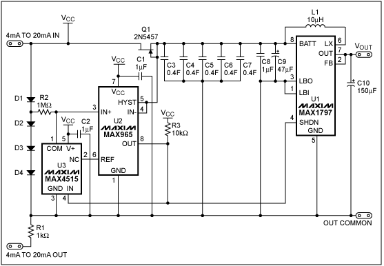
Current from the 4-20mA line runs through the four series connected diodes, which creates a pseudo-ground and a + 2.8V rail. The voltage drop created by the diodes (D1-D4) powers the low voltage comparator (U2) and switch (U3). The comparator monitors the super capacitor voltage unTIl it reaches the three-diode-drop threshold. Surpassing the threshold forces the comparator output to swing low, thus enabling the boost converter (U1) and closing the switch (U3). With the switch closed, the super capacitor voltage is compared against the + 1.235V internal reference of the comparator. 
Figure 1. A 2F capacitor bank (C3-C7) stores energy for later use. The boost converter (U1) generates a + 3.3V supply capable of delivering 250mA for up to 2.8 seconds.
ConnecTIng the gate and source of JFET Q1 together creates a current limiting diode. To maintain enough quiescent current (1mA) to power the comparator and switch, ensure that the saturation current (IDSS) of the JFET is less than or equal to 3mA.
The boost converter consumes between 400mA and 600mA when providing 250mA to the load. The boost converter's input current demand requires a super capacitor with an ESR well into the milliΩ region. Typical super capacitors do not meet this ESR requirement, as their ESRs are usually between 20Ω and 50Ω. Several BestCap® capacitors in parallel provide adequately low ESR and high storage capacity to meet the power requirements of the boost converter. 
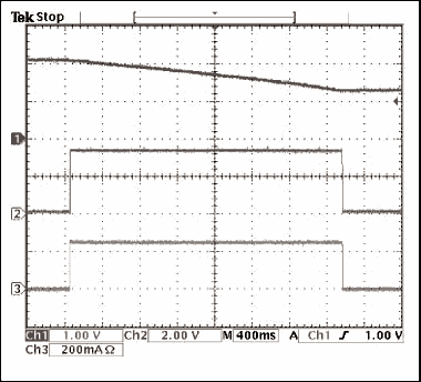
Figure 2. The boost converter turns on when the super capacitor reaches full charge, providing 250mA of current for approximately 2.8 seconds. (CH1: super capacitor voltage, CH2: output voltage, CH3: output current).
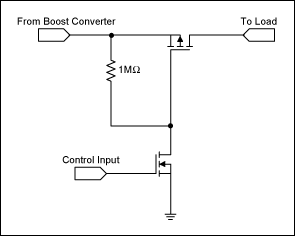
The integrated True-Shutdown â„¢ feature of the MAX1797 boost converter (U1) electrically disconnects the load from the power supply during shutdown. This feature prevents unwanted discharge of the super capacitor during the charging phase. You can prevent this discharge when using boost converters without True-Shutdown by configuring a pair of MOSFETs in the manner shown in Figure 3. 
Figure 3. The N-Channel MOSFET controls the gate of the P-Channel MOSFET to disconnect the output of the boost converter from the load.
A similar version of this article appeared in the May 2, 2002 issue of Selezione magazine.
True Shutdown is a trademark of Maxim Integrated Products, Inc.
Power Supply From 4-20mA Trans
When using a 4-20mA two-wire transmission system, it is useful to steal power for the remote device directly from the transmission line. It's not possible to draw large current from those lines but when the remote devices require large amounts of current for short periods, a big capacitor, or "super capacitor", can store energy to meet the short-duraTIon load. This applicaTIon note describes a circuit to achieve this.