With the rapid growth of the optical communication industry and the widespread deployment of fiber optic cables, ensuring the reliability and performance of optical networks has become a critical challenge for service providers. Traditional testing methods such as optical loss testing and OTDR (Optical Time Domain Reflectometry) have been widely used, but they come with limitations that make them less suitable for modern demands. Optical loss testing involves using a light source and an optical power meter to measure signal loss along the fiber link. While it is cost-effective and easy to operate, this method requires two technicians to perform and lacks the ability to precisely locate faults or identify their root causes. On the other hand, OTDR testing offers more detailed insights, including fiber length, attenuation, joint losses, and fault location. It is faster and more accurate, but its results are highly dependent on the operator's experience, making it difficult to achieve consistent and reliable outcomes without expert knowledge.
As network complexity increases, these traditional techniques are no longer sufficient to meet the growing demand for fast, accurate, and comprehensive testing. In response, the industry has introduced intelligent testing technologies based on OTDR principles. These new solutions incorporate link sensing technology, which allows for quick identification of the components in an optical link, analysis of its condition, and diagnosis of any failures. This advancement enables non-expert users to conduct thorough optical network tests efficiently and accurately, significantly improving operational efficiency and reducing downtime.
1. Link Sensing Technology Principle
Link-aware technology builds upon OTDR principles by performing multiple data acquisitions across different pulse widths. Short pulses are used to detect nearby sections of the fiber, while longer pulses are employed to analyze the far end. The collected data is then merged and analyzed comprehensively to determine the composition of the optical link and identify the cause of any faults. One of the main issues with traditional OTDR is the choice of a single pulse width. Using long pulses (over 320 ns) can result in information loss, especially when measuring connector attenuation, while short pulses (under 80 ns) may not penetrate beam splitters in PON networks, leading to incomplete end-to-end loss measurements. Link sensing technology overcomes these challenges by combining the strengths of both approaches, offering a more complete and accurate view of the optical network’s health.
The implementation of intelligent optical network testing involves injecting a specific optical pulse signal into the fiber and analyzing the backscattered and reflected signals to determine the link’s composition. The system includes a laser pulse transmitter, an optical signal receiver, and a signal acquisition circuit. On the software side, advanced data processing algorithms and visualization tools are used to interpret the results. The overall architecture is illustrated in Figure 1.
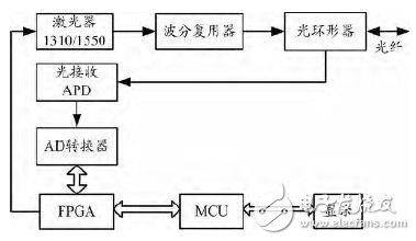
Figure 1: Overall scheme block diagram
Typically, the laser operates at either 1310 nm or 1550 nm wavelengths. The laser pulse transmitting circuit uses a high-speed FPGA to control the laser, generating precise pulse widths through accurate timing. It also adjusts the laser’s output power dynamically based on the pulse width. The receiving path employs an APD photodetector to convert the optical signal into an electrical one, followed by a high-performance operational amplifier to amplify the signal without distortion, thus enhancing the signal-to-noise ratio. The data acquisition circuit utilizes a high-speed parallel ADC chip to ensure accurate sampling and spatial resolution. Additionally, the FPGA performs initial data processing, and the MCU conducts intelligent analysis of the collected data to determine the composition and status of the fiber link, providing a comprehensive and reliable assessment of the network’s condition.
Ozone Aging Test Chamber,Oxidation Degree Testing Test Machine,Ozone Resistance Testing Test Box,Rubber Aging Test Machine
Wuxi Juxingyao Trading Co., Ltd , https://www.juxingyao.com