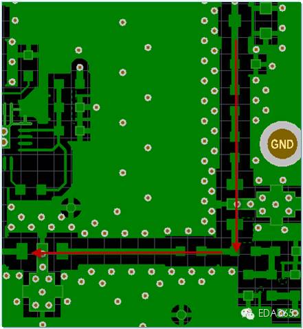
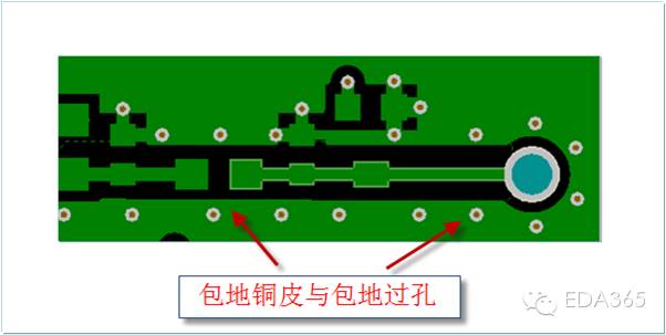
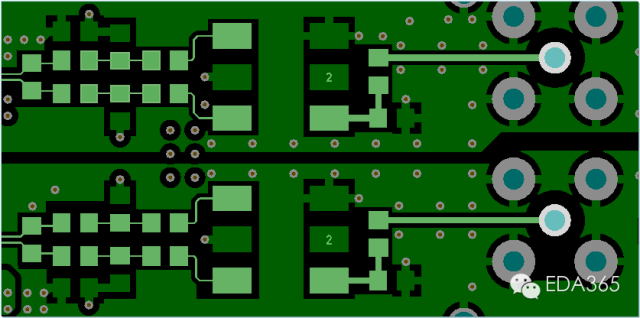
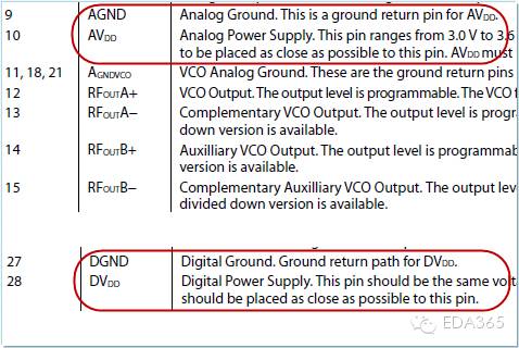
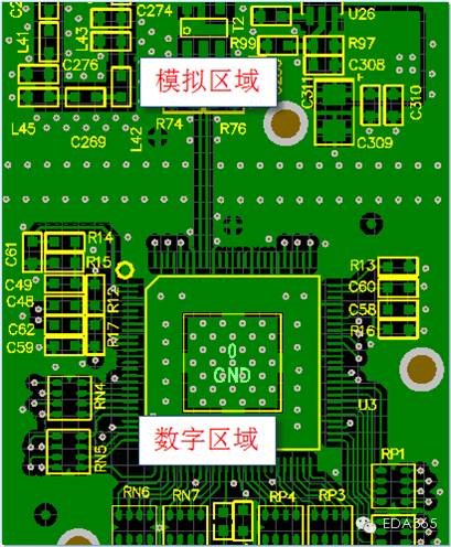
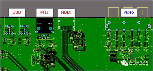
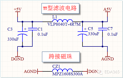
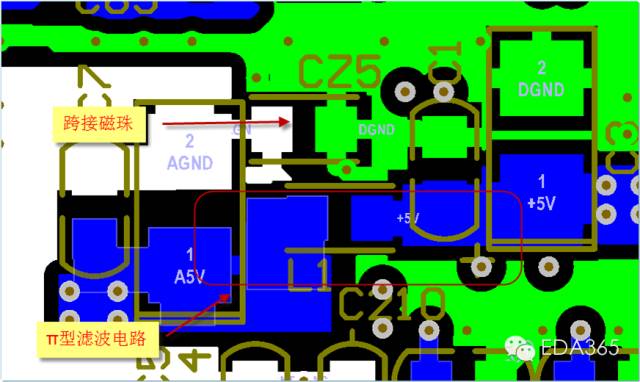
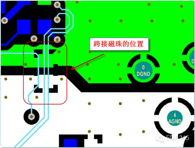
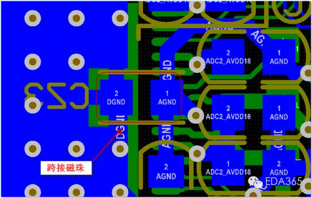
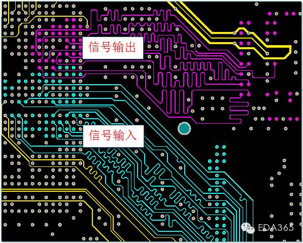
Strictly follow the order of the schematic diagram for layout and layout. The layout generally adopts a "one" or "L" layout. If the space permits, the analog signal should be processed with the package ground as much as possible. Pay attention that the package ground should be spaced not less than 200mil to drill ground vias. Try not to punch through holes for analog signals. The line width should be 10mil or more, and the trace should be short. For 50 ohm impedance, you can use the interlayer reference. Whether analog ground and digital ground should be separated mainly refer to the data manual (or schematic diagram). If the reference design of the AD converter chip is to use a unified digital ground, then when we are laying out, the digital devices and analog devices must be placed in partitions, and the partition is not divided. For the case where there is no designated analog interface device, generally follow the analog interface away from the power interface, digital interface (such as serial port, network port, HDMI, etc.). If the schematic diagram separates the analog ground from the digital ground, in principle, the power supply is not recommended to be divided. For the power supply across the division, it is recommended to use magnetic beads (or "Î " type filtering) to solve the problem. Add a digital ground and analog ground magnetic bead next to the magnetic bead across the boundary of the analog power supply for analog power and digital power return. For the signal line cross-segmentation, it can generally be solved by adding magnetic beads (or 0 ohm resistance) on the cross-segmented line. The A/D converter is placed across the analog-to-digital partition. Generally connect the analog ground and digital ground in A/D, or add magnetic beads for processing. If there are multiple channels of analog input or multiple channels of analog output, ground splitting should be done between each channel, and then single-point grounding should be done at the chip. The receiving and sending of the digital part are wired separately. Do not cross the wiring. The signal lines of the same group should be run in parallel, and the length should be equalized. The wiring spacing should meet 3W. 5G Outdoor Cpe,Outdoor 5G Cpe,Router 5G Cpe,Wireless Ap Router 5G Cpe Shenzhen MovingComm Technology Co., Ltd. , https://www.movingcommiot.com