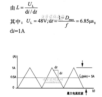
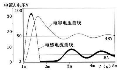
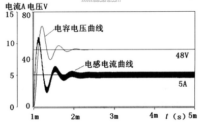
In today's article, we will bring you the design of the SABER control loop and the detailed settings of the main circuit parameters. Interested friends will take a quick look at the knowledge points. Control loop design method The first is the design method on the control loop. The system loop is an open loop BODE diagram. The slope of the amplitude at the shear frequency is -20 dB/dec and has a phase margin of at least 45°. The design steps for the control loop are as follows: 1. Design the main circuit according to the application requirements. 2. The BODE diagram of the main circuit is derived from the SABER simulator. 3. Determine the shear frequency ωc according to actual requirements and constraints. For power products, the shear frequency is usually 1/4 or 1/5 of the switching frequency. 4. Determine the type of compensation amplifier and each frequency point according to the requirements of the steady-state accuracy of the system and the shear frequency. The low frequency band is high, and the low frequency band of the general power product is designed as a type I system to ensure steady state accuracy; the slope at the mid-band bandwidth is -20 dB/dec, and there is sufficient phase margin (ie y" 45°) High-band gain attenuation is fast, reducing high-frequency interference; SABER is used to obtain the open-loop frequency response curve of the compensated loop, and the stability of the system is verified. Main circuit parameter setting Since the main circuit output filter parameters are related to the setting of the control loop, the compensator should be adjusted according to the output filter parameters. This article describes the design of the control loop with a 250W power supply example. Main technical requirements Input: AC220V [DC=265V (220~310V)] Output: 48V 0.5 ~ 5A; Ripple voltage: 0.1V; ripple current: 1A; Efficiency: ≥0.85; switching frequency: 100kHz; Transformer primary side ratio n=2; Uout=48.85V (diode); duty cycle: Output filter parameter The output filter is designed according to the required ripple current and ripple voltage value. The ripple current determines the inductance value. The ripple current and the ripple voltage together determine the capacitance value. Filter inductor figure 1 The waveform of the flowing inductor current is shown in Figure 1. The peak-to-peak value of the ripple current depends on the minimum allowable current value. When the load current is less than 0.5A, it enters the current interrupt mode. To prevent the converter from entering the discontinuous mode, the current through L cannot fall to zero during Toff. Filter capacitor The capacity of the filter capacitor is discussed in the following two cases: A common aluminum electrolytic capacitor is used. When the switching frequency is lower than 500 kHz and the RoCo is greater than half of the off and on time of the switching transistor, the output ripple is determined only by ESR (Ro). This method becomes impractical with advances in technology, and it is best to obtain the ESR value of the capacitor from the manufacturer or test. figure 2 image 3 The filter capacitor uses zero ESR or low ESR capacitor, and the zero point (1/2πRest & TImes; C) formed by its own RC is higher, but has little effect on the loop design; if the capacitor with low ESR value has large capacity, its own RC The resulting zero point makes the high frequency attenuation near the bandwidth insufficient, which may cause oscillation and increase the design difficulty of the compensator. As shown in Figure 2 and Figure 3. Consider the heat of the capacitor affecting the lifetime, taking 22μF. The maximum value of the ESR value of the capacitor is: ESR(max) = ΔU / ΔI = 0.1 / l = 0.1 Ω. When the ESR exceeds 0.1 Ω, the ripple voltage increases. Through the introduction of this article, I believe that you have a better understanding of the control loop design and the detailed setting of the main circuit parameters using SABER dual-tube forward. SABER is a powerful simulation software. Using this software can save designers a lot of design time and input cost. In the following articles, Xiaobian will continue to introduce you, please pay attention to it. Brightness Led Outdoor Lamp,Led Moisture Proof Lamp,Ip65 Waterproof Led Lamp,Moisture Proof Lamp jiangmen jieken lighting appliance co.,ltd , https://www.jekenlighting.com