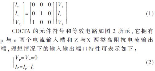
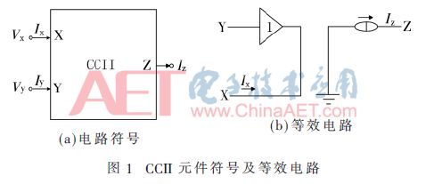
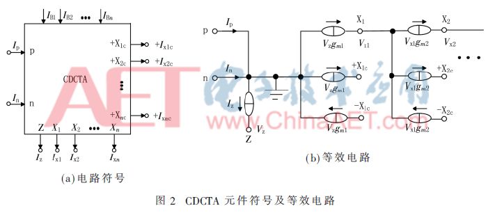
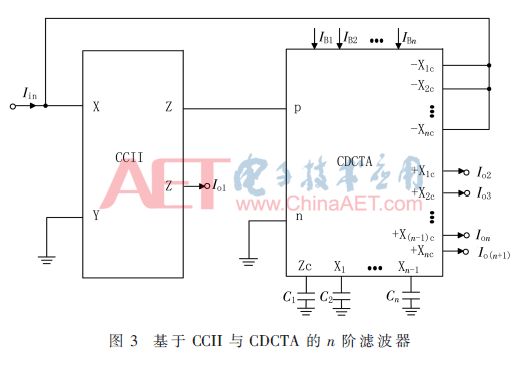
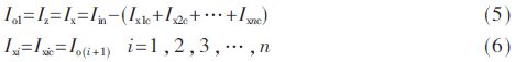
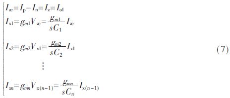
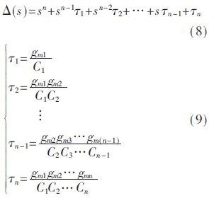
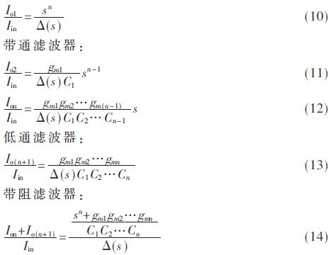
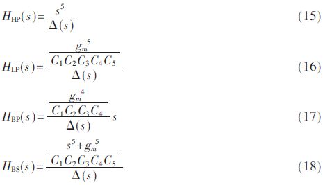
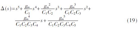
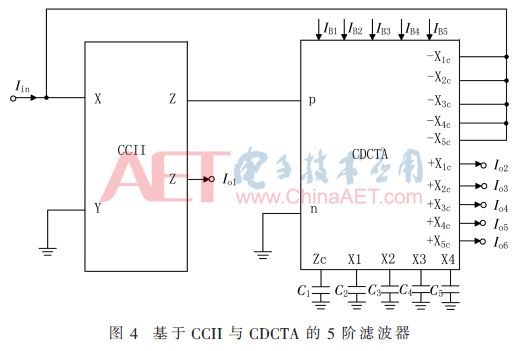
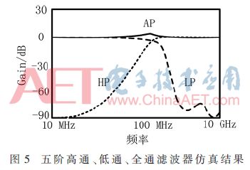
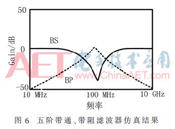
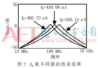
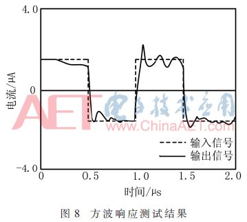
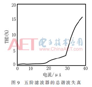
Aiming at the problems of high power consumption and narrow bandwidth of high-order filters, a current mode n-order multifunctional filter is proposed. The circuit consists of only a second-generation current conveyor (CCII), a current differential cascaded transconductance amplifier (CDCTA), and a grounded capacitor. The circuit structure is simple, the power consumption is as low as 6.82 mW, the sensitivity is less than 1, the 3 dB bandwidth is greater than 100 MHz, and the bandwidth can be electrically controlled and tuned. PSpice simulation and hardware experiment test results show that the designed circuit is correct and effective. 0 Preface Continuous-time filters have broad application prospects in computer, communications, electronics, intelligent control and other industries. They are based on the second generation current conveyor (CCII), operational amplifier (Operational Transconductance Amplifier, OTA), current differential trans The design of second-order current mode filter circuits for various active devices such as Current Differencing Transconductance Amplifier (CDTA) has been reported [1-6]. CCII has become a basic active device because of its strong versatility, flexibility and wide gain bandwidth product. CDCTA is a pure current mode active device proposed after the current differential transconductance amplifier CDTA, which has the characteristics of high flexibility, low power consumption, frequency bandwidth, and electrically controllable tuning [7]. Although the design of continuous-time filters based on various active devices is relatively mature, high-order filters are still relatively rare, especially high-order filters realized by combining different devices [8-10]. In this paper, only two active devices, CCII and CDCTA, are used to design an n-order multi-function filter, which has the characteristics of simple circuit structure, low power consumption, bandwidth, low sensitivity and electronic control tuning. 1 CCII and CDCTA port characteristics and circuits CCII is a current mode device with current transfer function. Its circuit symbol and equivalent circuit are shown in Figure 1. CCII has two input terminals X and Y and a current follower output terminal Z. The ideal transmission characteristics can be described by the following matrix. Among them, gmi is the i-th transconductance gain, which can be controlled by the bias current IBi, and Vz and Vxi are the voltage drops on the output ports Z and Xi (assuming an external impedance is connected to the port). Vz and Vxi are transformed into output currents Ix1c and Ixic of the next stage through transconductance. Design of 2 n-order multifunctional filter Figure 3 shows the multifunctional active filter circuit based on CCII and CDCTA. It only needs one CCII, one CDCTA and n grounding capacitors to achieve n-order low pass, high pass, band pass, band stop and full Pass filter function function. Therefore, this structure is greatly simplified compared with the traditional n-order filter circuit, and is very suitable for integration. As shown in Figure 3, Iin is the input signal of the filter, and Ioi is its output signal. According to Figure 3 and formula (1) ~ formula (4), the circuit output equation is: High pass filter: It can be seen from the above equation that the high-pass, band-pass, and low-pass filter functions can be obtained directly from the Io1, Ioi, and Io(n+1) of the circuit, and their frequency bands can be tuned electronically by gm. In addition, if you need to generate bandstop and all-pass filter functions, you only need to select Io1 to Io(n+1) to easily accumulate and sum. 3 Design examples In order to prove the availability of the n-order multi-function filter proposed above, a current-mode fifth-order multi-function filter is designed, as shown in Figure 4. Assuming that the bias currents are all equal values, calculated according to equations (10) to (14), we can get: 4 Computer simulation In order to verify the above theoretical analysis, a fifth-order Butterworth filter with a cut-off frequency of 100 MHz is designed, and the Δ(s) function is: In order to minimize the impact of active devices on the performance of the designed filter, the second-generation current conveyor [2] takes plus or minus 1.25 V for the input voltage, and Io takes 50 μA, I1=I2=I3=100 μA. CDCTA[11] power supply settings are as follows: VDD=-VSS=1.25 V, Io=50 μA, IA=100 μA. To facilitate the calculation, take gm=100 μS, and take IB=IB1=IB2=IB3=IB4=IB5=450.08 μA by tuning the bias current. According to the set circuit parameters, the TSMC 0.18 μm CMOS model is used to simulate the designed fifth-order multi-function filter in PSpice. In order to make the 3 dB cutoff frequency of the filter 100 MHz, according to the special function of the fifth-order filter and equations (15)~(19), the capacitance of the passive filter is C1=3.090 μF, C2=6.168 μF, C3 =10.021 pF, C4=1.490 pF, C5=3.468 pF. The simulation results are shown in Figure 5 and Figure 6. The measured 5th-order filter 3 dB cut-off frequency is 99.88 MHz. In order to verify that the proposed filter frequency band can be electrically controlled and tuned, when the bias current of CDCTA is set to IB=400.22 μA, IB=450.08 μA, IB=500.14 μA, the theoretical center frequency of the fifth-order low-pass filter is 80 MHz respectively , 100 MHz, 120 MHz, the simulation result is shown as in Fig. 7. Obviously, the bandwidth of the proposed high-order filter can be electronically tuned. In order to verify that the designed filter has stable transmission response characteristics, a fifth-order low-pass filter is selected for a square wave test. The test results are shown in Figure 8. At the same time, in order to analyze the total harmonic distortion (THD) of the circuit, when the input signal is a 50 MHz sinusoidal input signal, the THD simulation result is shown in Figure 9. Obviously, when the current of the fifth-order filter circuit is less than 30 μA, the total harmonic distortion of the circuit is less than 3.5%. In addition, the simulation results show that the circuit has extremely low power consumption, and the test power consumption is only 6.82 mW. 5 Conclusion This paper proposes a pure current mode continuous-time high-order filter, which only uses two active devices CCII and CDCTA and n grounding capacitors. The circuit has the following advantages: (1) Only two active devices are included, and the structure is simple; (2) No passive resistance, easy to integrate; (3) Low voltage, low power consumption; (4) Frequency bandwidth, wide application range; (5) Low pass, high pass, band pass, band stop and all pass can be realized 5 kinds of filtering functions; (6) Frequency band can be electronically controlled and tuned; (7) Low sensitivity and low distortion. Based on these characteristics, the multifunctional filter can be used in common scenarios such as source filtering and interference signal filtering in the field of communication signal processing. Nintendo Switch Joy-Con,Nintendo Switch Console,Nintendo Switch Console Game,Nintendo Switch Joycons Shenzhen GEME electronics Co,.Ltd , https://www.gemesz.com