Since Codivilla reported bone lengthening in 1904, limb lengthening has been developed for more than 100 years. The theory of slow bone retraction has been formed and constantly improved, and at the same time limb extension devices are constantly evolving. At present, the surgical techniques and instruments for limb extension have undergone three stages of development [1]: (1) external fixation of the stent; (2) intramedullary nail combined with external fixation; and (3) fully implantable limb extender. The external fixation device adopts manual external force control to realize the stretching of the orthosis. The control precision of the stretching is low, the operation is difficult, and the needle infection is easily caused in clinical application, which is not conducive to the healing of the bone in the prolonged area, and at the same time, it is carried for a long time. The fixator also has an adverse effect on the patient's physical and psychological. Intramedullary nail combined with external fixation technique has made great progress in stability and extension accuracy, but it still cannot avoid the adverse consequences brought by external fixation. The fully implantable bone extender has become the development direction of the bone extender because of its built-in power generating device, which can accurately control the elongation rate while avoiding the problem of needle infection. At present, the most mature and representative of this technology is the intramedullary internal bone dynamic extender (ISKD) developed by ORTHOFIX. It consists of an external monitor and a surgically implanted telescopic telescope barrel-like intramedullary nail. Composition, the basic principle is to rely on the rotation of the joint movement of the patient to drive the internal stretcher to stretch. However, its shortcoming is that it can only be stretched and can not be retracted and pressurized. Once the activity is large, it exceeds the length of a single stretch and cannot be retracted. It may lead to the failure of the broken bone surface to grow, and there is a great risk of clinical application. This article refers to the address: http:// To meet the user's portability requirements, the orthosis system is battery powered. Therefore, low power consumption is a major indicator of the system. For this reason, the system selects MSP430 series single-chip microcomputer with ultra-low power consumption characteristics. Based on the MSP430F169 microcontroller, the system platform is built, and the software interrupt processing mechanism is used to achieve the low power consumption of the system. High-precision control is another major indicator of the system. The orthosis must maintain high-precision stretch and retraction control, and any error will have adverse effects on the user. The system uses the ZP series sensor to return the micro motor running signal, and the signal is amplified and processed and sent back to the MCU for precise control. According to the software design, the system achieves an operating accuracy of 0.1 mm, which is much more accurate than existing orthoses. 2.2.2 Motor drive <br> The internal precision motor of the orthosis has a maximum withstand voltage of 6 V, and its drive voltage is about 4 V. For every 1 V drop, the motor speed drops by 2 800 r/m, so the motor is driven. Not only does the circuit require a large amount of drive capability, but its output also requires high stability. 2.2.3 Parameter feedback <br> This design requires precise control of the bone orthosis while maintaining the low power consumption of the system. Therefore, the ZP series zero-power magnetic sensor is installed inside the bone orthosis, which is a kind of work. The new sensor does not require an external power supply, and the dual magnetic pole alternately triggers the working mode. The turntable is mounted on the motor shaft, and a small magnet is fixed on the turntable. When the turntable rotates and the small magnet passes directly under the magnetosensitive element, the magnetosensitive element generates an electrical signal, and the electrical signal is transmitted to the peripheral circuit through the wire, and the amplitude of the electrical signal is The rate of change of the magnetic field is independent. 3.2 Motor Control <br> The speed regulation function of the orthosis is realized by the PWM B wave output from the timer B of the MSP430F169 [5]. By changing the value in the capture/compare registers CCR1, CCR2, the duty cycle of the 2-way (P4.1, P4.2) PWM square wave signal generated by timer B can be changed by changing the value in the capture/compare register CCR0. The cycle of the PWM square wave signal can be changed, thereby achieving the purpose of changing the rotational speed of the micromotor. When the P4.1 outputs the PWM signal, the orthosis is running in the forward direction; when the P4.2 outputs the PWM signal, the orthosis is reversed; when both P4.1 and P4.2 are output or no signal is output, the orthosis stops. run. This paper introduces the design and implementation of a new type of high precision self-controlled bone orthosis. The bone orthosis is placed in the long bone marrow cavity to avoid high complications of the external fixation device, and can be used as an internal fixator and a stretch function, and can achieve a long-lasting and stable stretch after a single stretch. The effect is that the limb distraction surgery has small trauma, simple operation and postoperative care; the performance is safe and reliable, the operation is simple, stable and practical, and does not bother the patient's daily life. In practical application, the effect is obviously superior to the traditional bone orthosis, which is very high. Practical value.
Automotive Fuse
Automotive Fuse, ie Car Fuse, is the name we are often called. Its official name is "fuse protector." The use of Automotive Fuse Block is very similar to that of household fuses, which act as a circuit protection barrier when the circuit current is abnormal and exceeds its rated current. Vehicle fuses are broadly divided into two types of fast-blow fuses and slow-blow fuses.
A car is made of Car Fuse, Automotive Switches and other kinds of Automotive Accessories, and the Automotive Switches including Automotive Rotary Switches, Automotive Battery Switches, Automotive Rocker Switches
Inline Fuse Holder include high-current fuses and medium-low current fuses. Medium and low current fuses are generally easier to reach. Low-to-medium current fuses can be broadly classified as chip fuses (including automatic fuse box mini-fuse), plug-in fuses, screw-on fuses, and tube fuse box fuses. Among them, we are able to access medium-sized ATO or small-size fast-acting chip fuses. Chip fuses can carry small currents, short pulse currents, such as headlamp circuits, post-glass defrosting, and more.
Car Fuse,Automotive Fuse,Automotive Mini Fuses,Automotive Fuses Types YESWITCH ELECTRONICS CO., LTD. , https://www.yeswitches.com
At present, the surgical techniques and instruments for limb extension in China are still in the second stage [2], far behind developed countries. In China's national medium- and long-term science and technology development program, the research and development of new medical devices has been taken as a new field to encourage investment and independent innovation. To this end, this paper designed a high-precision, self-controlled bone orthosis with MSP430F169 microcontroller as the core. The bone orthosis not only overcomes the shortcomings of the external fixator, but also overcomes the disadvantage that the ISKD cannot be retracted and pressurized. The motor control is simple and convenient, and the user can automatically control the expansion and contraction of the bone orthosis according to the need, and the extension precision is high, and has broad application prospects.
1 System design <br> The system consists of an internal bone orthosis implanted in the long bone marrow cavity and an external controller. The external controller is connected to the internal bone orthosis through the bio-silicon tube lead, and is mainly composed of MSP430F169 single-chip microcomputer, motor drive circuit, power module, signal processing module, keyboard and liquid crystal display system. The bone orthosis in the body realizes self-expansion through the operation of the precision motor, and the single-chip microcomputer realizes the precise control of the bone orthosis through the parameter feedback module and the signal processing module formed by the magnetic sensitive sensor. The overall structure of the system is shown in Figure 1. 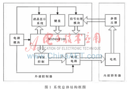
2 system hardware design
2.1 MSP430F169 single-chip MSP430F169 [3] single-chip microcomputer is a 16-bit single-chip microcomputer with ultra-low power consumption and powerful function produced by Texas Instruments. It uses the "von Neumann" structure, RAM, ROM and all peripheral modules are located in the same address space, the maximum addressing address is 62 KB; with powerful interrupt function, 48 I / O pins, each The I/O ports correspond to multiple registers such as input, output, function selection, and interrupt. The functions of the function and the general I/O port can be realized by selecting the function to be implemented before operating the same I/O port. It greatly enhances the function and flexibility of the port; MSP430F series ultra-single-chip self-contained flash memory, when operating under 1 MHz clock condition, the working current is only 0.1 ~ 280 μA depending on the working mode; at the same time it has good Simulation development technology, set up with JTAG emulation interface and high-level language compiler.
2.2 Bone orthosis system
2.2.1 The mechanical structure of the orthosis mechanical orthosis is shown in Figure 2. In the figure, the left end (1) and the right end (11) are respectively fixed to the external components by screws. The left end (1) and the motor (3), the motor bracket (4) and the outer sleeve (7) are fixed together by interference and are left end parts. The right end (11) and the inner sleeve (8) are fixed together by means of a thread and are right end parts. There is a guiding key (6) between the inner sleeve and the outer sleeve, which can limit the mutual circumferential rotational movement between the inner sleeve and the outer sleeve, and realize the length direction and the stroke range (100 mm). Free movement. The sliding along the length between the left end piece and the right end part is achieved by the motor. The motor output is decelerated by the reducer, and the output shaft of the motor reducer rotates the center screw (9) through the thin button of the motor, and then the center screw is pushed by the thread to push the inner sleeve of the guide key circumferentially fixed, thereby realizing the expansion and contraction of the entire system. . Precise control of the motor is at the heart of the entire orthosis system. 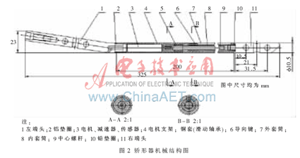
This design uses the motor-specific control chip LG9110 [4] as the drive circuit of the motor. The chip is a 2-channel push-pull power amplifier ASIC designed for control and drive motors. It integrates discrete circuits into a single IC, eliminating the need for any peripheral components, reducing application costs and improving the overall machine. reliability. The LG9110 has good anti-interference ability and large current drive capability. The two outputs can directly drive the forward and reverse movement of the motor. The motor drive circuit is shown in Figure 3. The 6-pin of the LG9110 is connected to the forward signal, the 7-pin is connected to the reverse signal, and the 1st and 4th pins are connected to the precision motor. 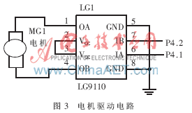
2.2.4 Signal Processing The output signal of the ZP series sensor is very small. The output pulse signal after the signal is subjected to the post-amplification processing is shaped by the 74HC14 and sent to the MCU for counting. The 16-bit timer A with timing/capture function of the MSP430F169 is used to count the pulse. The external pin signal is used as the input clock source of timer A. The operating mode of timer A is incremented to CCR0 mode.
2.3 Keyboard Display <br> In order to reduce the system power consumption and reduce the number of I/O ports that occupy the MCU, the keyboard module is designed as a 3×3 button determinant keyboard, which is processed by interrupt mode, P2.0~P2.2 Line line, P2.5~P2.7 as the column line. As long as the button is pressed, it will trigger an interrupt, enter the keyboard processing program, realize the initial displacement, target displacement, control the forward, reverse and read of the bone orthosis micro-motor, save data and other functions.
The orthosis needs to provide users with rich interactive information. This design uses HG1286413 monochrome dot matrix graphic liquid crystal display as the user's interactive interface, which can display up to 4 rows, 8 columns and 32 characters. P3.0~P3.7 is used as the data line of liquid crystal, P5.4~5.7 is used as liquid crystal enable, internal command register/display memory selection control and read/write mode control bit, and P5.3 is the control bit of reset signal. The LCD display displays information such as operation prompts, working status, and battery undervoltage alarms for the user.
2.4 Power Module <br> The motor has great interference to the power supply during normal operation. In order not to affect the normal operation of the MCU, the system uses dual power supply and is powered by a 5 V/4.8 Ah lithium battery. One group is converted to 3.3 V by AMS1117 to supply power to the MCU and peripheral circuits; the other set of DC/CD module B0505S-1W with very low ripple is used to supply power to the motor.
The driving voltage of the LG9110 should not be lower than 4 V, otherwise the motor will not work properly. A voltage detection circuit is designed for this purpose. The reverse input terminal P2.4 of the comparator A inside the MSP430F169 is taken from the voltage dividing resistor, and the non-inverting input terminal is the reference voltage. The internal voltage VCC/2 is selected, which is 1.65 V. When the battery voltage is lower than the set value of 4 V, the trigger comparator A is interrupted, the program enters the low-voltage service program, saves the field data to the information memories A, B, and prompts the user to charge the battery. When the voltage changes between 4 V and 5.0 V, the circuit does not cause erroneous operation.
3 system software design
3.1 Main Programs <br> In order to reduce the burden on the CPU and reduce the power consumption of the circuit, all functions of the system are implemented by using the interrupt method. After the main program performs some necessary initialization work, it enters a low-power dead loop state and waits for an interrupt. Once there is an interrupt, the CPU wakes up from the low-power mode, performs interrupt processing, and returns to the low-power dead loop again after the interrupt ends. The flow chart of the main program is shown in Figure 4. 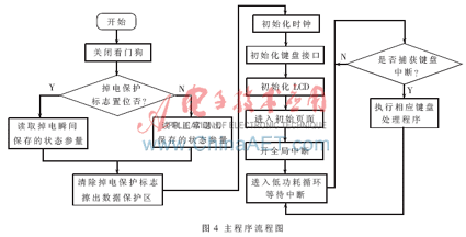
The orthosis running displacement is determined by the number of pulses recorded by timer A. The micromotor has a speed of 8 000 r/m and is decelerated by the reducer 4 096:1. The output speed is 1.95 r/m, so the center screw speed is also 1.95 r/m, and the center screw has a thread lead of 0.5. Mm. Therefore, the running speed of the inner sleeve relative to the outer sleeve is 0.975 mm/min, and the running speed of the entire orthosis is 0.975 mm/min. According to the calculation, the micromotor runs 819.2 rpm for every 0.1 mm of the orthosis, and 4 small magnets are fixed on the code wheel, and the counter records 3 277 pulses. The user selects the current running displacement through the keyboard, and the program controls the precise displacement of the orthotic operation displacement by setting the CCR0 value. The motor control program flow chart is shown in Figure 5. 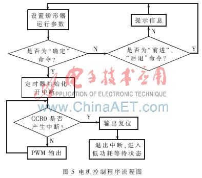
references
[1] Zhang Tao, Pang Guigen. Research progress of limb lengthening[J]. Chinese Journal of Bone and Joint Injury, 2008, 23(3): 262-264.
[2] Zhao Huisan. Rehabilitation of limbs for 20 years: development and challenges of prosthetic orthotics service [J]. Chinese Journal of Orthopaedics, 2007, 15 (7): 481-483.
[3] Wei Xiaolong. MSP430 series MCU interface technology and system design example [M]. Beijing: Beijing University of Aeronautics and Astronautics Press, 2002.
[4] Zhuang Wei, Song Guangming, Wei Zhigang, et al. Design and implementation of wireless sensor network nodes with mobility capability [J]. Journal of Jilin University (Engineering Edition),
2007, 37(4): 939-943.

