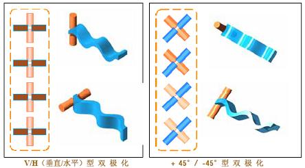
1.4 Polarization of the antenna The antenna radiates electromagnetic waves into the surrounding space. Electromagnetic waves are composed of electric and magnetic fields. People stipulate that the direction of the electric field is the antenna polarization direction. The commonly used antenna is single-polarized. The figure below shows two basic cases of single polarization: vertical polarization is the most commonly used; horizontal polarization is also used. The following figure shows that two single-polarized antennas are installed together to form a dual-polarized antenna. Note that the dual-polarized antenna has two connectors. A dual-polarized antenna radiates (or receives) two polarized waves that are orthogonal (perpendicular) to each other in space. 1.5 Input impedance of the antenna Zin 1.6 Operating frequency range of antenna (band width) 1.7 Base station antennas, repeater antennas and indoor antennas commonly used in mobile communications 2 Several basic concepts of radio wave propagation The frequency bands currently used by GSM and CDMA mobile communications are: Used in electronic products, Computers ,mobile phone Dongguan Bofan technology Co., LTD , https://www.ufriendcc.com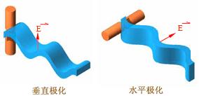
1.4.1 Dual-polarized antenna The following figure shows two other types of single-polarization: + 45 ° polarization and -45 ° polarization. They are only used in special occasions. In this way, there are four kinds of single polarization, see the figure below. A combination of vertically polarized and horizontally polarized antennas, or a combination of + 45 ° and -45 ° polarized antennas, constitutes a new type of antenna --- Dual-polarized antenna. 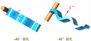
1.4.2 Polarization loss Vertically polarized waves should be received by antennas with vertical polarization characteristics, and horizontally polarized waves should be received by antennas with horizontal polarization characteristics. Right-handed circularly polarized waves should be received with antennas with right-handed circular polarization, while left-handed circularly polarized waves should be received with antennas with left-handed circular polarization.
When the polarization direction of the incoming wave is different from the polarization direction of the receiving antenna, the received signal will become smaller, that is, polarization loss occurs. For example: when using a + 45 ° polarized antenna to receive vertically polarized or horizontally polarized waves, or when using a vertically polarized antenna to receive + 45 ° or -45 ° polarized waves, etc. To produce polarization loss. If a circularly polarized antenna is used to receive any linearly polarized wave, or if a linearly polarized antenna is used to receive any circularly polarized wave, etc., polarization loss will inevitably occur-only the incoming wave can be received Half energy.
When the polarization direction of the receiving antenna is completely orthogonal to the polarization direction of the incoming wave, for example, use a horizontally polarized receiving antenna to receive vertically polarized incoming waves, or use a right-handed circularly polarized receiving antenna to receive left-handed circularly polarized When an incoming wave arrives, the antenna cannot receive the incoming wave energy at all. In this case, the polarization loss is the largest, and the polarization is said to be completely isolated.
1.4.3 Polarization isolation There is no ideal polarization isolation. The signal fed to one polarized antenna will always appear a little bit in another polarized antenna. For example, in the dual-polarized antenna shown in the figure below, suppose that the power input to the vertically polarized antenna is 10W, and as a result, the output power measured at the output end of the horizontally polarized antenna is 10mW. 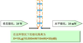
Definition: The ratio of the signal voltage to the signal current at the input of the antenna is called the input impedance of the antenna. The input impedance has a resistance component Rin and a reactance component Xin, that is, Zin = Rin + j Xin. The presence of the reactive component will reduce the antenna's extraction of signal power from the feeder. Therefore, the reactive component must be as low as possible, that is, the input impedance of the antenna should be as pure as possible. In fact, even an antenna that is well designed and debugged always contains a small reactance component in its input impedance.
The input impedance is related to the structure, size, and operating wavelength of the antenna. The half-wave symmetrical oscillator is the most important basic antenna. Its input impedance is Zin = 73.1 + j42.5 (Europe). When the length is shortened by (3 ~ 5)%, the reactance component can be eliminated, and the input impedance of the antenna is pure resistance. At this time, the input impedance is Zin = 73.1 (Euro), (nominal 75 Euro). Note that strictly speaking, the input impedance of a purely resistive antenna is only for the point frequency.
By the way, the input impedance of a half-wave oscillator is four times that of a half-wave symmetric oscillator, that is, Zin = 280 (Euro), (nominal 300 Euro).
Interestingly, for any antenna, one can always adjust the antenna impedance. Within the required operating frequency range, the imaginary part of the input impedance is very small and the real part is quite close to 50 ohms, so that the input impedance of the antenna is Zin = Rin = 50 ohms-this is necessary for the antenna to be in good impedance matching with the feeder.
Regardless of whether it is a transmitting antenna or a receiving antenna, they always work within a certain frequency range (band width). There are two different definitions of the antenna band width ------
One is: under the condition of standing wave ratio SWR ≤1.5, the working frequency bandwidth of the antenna;
One is: the bandwidth of the antenna within a range of 3 dB.
In the mobile communication system, it is usually defined according to the former one. Specifically, the bandwidth of the antenna is the working frequency range of the antenna when the SWR of the antenna does not exceed 1.5.
Generally speaking, the antenna performance is different at each frequency point within the operating frequency bandwidth, but the performance degradation caused by this difference is acceptable.
1.7.1 Plate antenna Whether it is GSM or CDMA, the plate antenna is the most commonly used type of extremely important base station antenna. The advantages of this kind of antenna are: high gain, good sector pattern, small rear lobe, vertical plane pattern depression angle control, reliable sealing performance and long service life.
The plate antenna is also often used as the user antenna of the repeater. According to the size of the sector area, the corresponding antenna model should be selected.
1.7.1 a Example of basic technical indicators for base station panel antennas Frequency Range 824-960 MHz Bandwidth 70MHz Gain 14 ~ 17 dBi polarization vertical Nominal impedance 50 Ohm Voltage standing wave ratio ≤1.4 Front to back ratio > 25dB Downtilt angle (adjustable) 3 ~ 8 ° Half power beam width Horizontal plane 60 ° ~ 120 ° vertical plane 16 ° ~ 8 ° Vertical sidelobe suppression <-12 dB Intermodulation ≤110 dBm
1.7.1 b Formation of high gain of plate antenna
A. Use multiple half-wave dipoles to form a linear array placed vertically 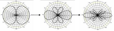
Single half-wave dipole vertical plane pattern Two half-wave dipole vertical plane pattern Four half-wave dipole vertical plane pattern 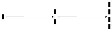
Single half wave oscillator Two half wave oscillators Four half wave oscillators
B. Add a reflector on one side of the linear array (take the vertical array of two-half wave oscillator with reflector as an example) 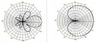
Two half-wave dipoles Two half-wave dipoles (with reflector) (with reflector)
Vertical plane pattern Horizontal plane pattern Gain is G = 11 ~ 14dBi 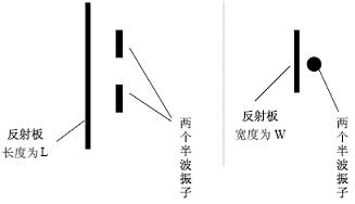
Two half wave oscillators (with reflector) Two half wave oscillators (with reflector)
Arrangement on vertical plane Arrangement on horizontal plane
C. In order to increase the gain of the plate antenna, eight half-wave dipole arrays can be further used. It has been pointed out that the gain of four half-wave dipoles arranged in a vertical linear array is about 8 dBi; The four-element linear array of the reflector, that is, the conventional plate antenna, has a gain of about 14 to 17 dBi.
An eight-element linear array with a reflector on one side, that is, an elongated plate antenna, has a gain of about 16 to 19 dBi. It goes without saying that the length of the elongated plate antenna is double that of the conventional plate antenna, reaching about 2.4 m.
1.7.2 High-gain grid parabolic antenna From the perspective of cost performance, people often choose grid parabolic antenna as the donor antenna of repeater. Due to the good focusing effect of the parabolic surface, the parabolic antenna has a strong collecting ability, and the grating parabolic antenna with a diameter of 1.5 m has a gain of G = 20dBi in the 900 megaband. It is particularly suitable for point-to-point communication, for example, it is often selected as the donor antenna of repeaters. The parabolic surface adopts a grid structure, one is to reduce the weight of the antenna, and the other is to reduce the resistance of the wind.
Parabolic antennas can generally give a front-to-rear ratio of not less than 30 dB, which is exactly the technical index that the repeater system must meet for the receiving antenna to prevent self-excitation.
1.7.3 Yagi directional antenna Yagi directional antenna has the advantages of high gain, light structure, convenient installation, and low price. Therefore, it is particularly suitable for point-to-point communication, for example, it is the preferred antenna type for outdoor receiving antennas of indoor distribution systems.
The greater the number of Yagi directional antennas, the higher the gain. Generally, 6 to 12 units of Yagi directional antennas are used, and the gain can reach 10-15dBi.
1.7.4 Indoor ceiling antenna The indoor ceiling antenna must have the advantages of light structure, beautiful appearance, and easy installation.
The indoor ceiling antennas seen on the market today have many shapes and colors, but the purchase and manufacture of their inner cores are almost the same. The internal structure of this ceiling antenna, although small in size, is based on the antenna broadband theory, with the aid of computer-aided design, and the use of a network analyzer for debugging, so it can well meet the needs of a very wide range of work For the standing wave ratio in the frequency band, according to national standards, the antenna operating in a wide frequency band has a standing wave ratio index of VSWR ≤ 2. Of course, it is better to achieve VSWR ≤ 1.5. By the way, indoor ceiling antennas are low-gain antennas, generally G = 2 dBi.
1.7.5 Indoor wall-mounted antennas Indoor wall-mounted antennas must also have the advantages of light structure, beautiful appearance, and easy installation.
The indoor wall-mounted antennas seen on the market today have many shapes and colors, but the purchase and manufacture of their inner cores are almost the same. The internal structure of this wall-mounted antenna belongs to an air dielectric microstrip antenna. Because the auxiliary structure of widening the antenna bandwidth is adopted, with the aid of computer-aided design, and debugging using a network analyzer, it can better meet the requirements of working wide frequency band. By the way, the indoor wall-mounted antenna has a certain gain, about G = 7 dBi.
GSM: 890-960 MHz, 1710-1880 MHz
CDMA: 806-896 MHz
The frequency range of 806-960 MHz belongs to the ultrashort wave range; the frequency range of 1710 ~ 1880 MHz belongs to the microwave range.
If the frequency of the radio wave is different, or the wavelength is different, its propagation characteristics are not exactly the same, or even very different.
2.1 The free space communication distance equation assumes that the transmission power is PT, the transmission antenna gain is GT, and the operating frequency is f. The reception power is PR, the reception antenna gain is GR, and the distance between the receiving and transmitting antennas is R. , The radio wave loss L0 during propagation has the following expression:
L0 (dB) = 10 Lg (PT / PR)
= 32.45 + 20 Lg f (MHz) + 20 Lg R (km)-GT (dB)-GR (dB)
[Example] Let: PT = 10 W = 40dBmw; GR = GT = 7 (dBi); f = 1910MHz
Q: When R = 500 m, PR =?
Answer: (1) Calculation of L0 (dB)
L0 (dB) = 32.45 + 20 Lg 1910 (MHz) + 20 Lg 0.5 (km)-GR (dB)-GT (dB)
= 32.45 + 65.62-6-7-7 = 78.07 (dB)
(2) Calculation of PR
PR = PT / (10 7.807) = 10 (W) / (10 7.807) = 1 (µW) / (10 0.807)
= 1 (µW) / 6.412 = 0.156 (µW) = 156 (mµW)
By the way, when a 1.9GHz radio wave penetrates a brick wall, it loses approximately (10 ~ 15) dB
2.2 Propagation line-of-sight of ultrashort wave and microwave
2.2.1 Extreme direct viewing distance Ultrashort waves, especially microwaves, have high frequencies and short wavelengths, and their surface wave attenuates quickly, so they cannot rely on surface wave propagation for longer distances. Ultrashort waves, especially microwaves, are mainly propagated by space waves. Simply put, a space wave is a wave that propagates in a linear direction in the spatial range. Obviously, due to the curvature of the earth, there is a limit of the direct view distance Rmax for space wave propagation. The area within the farthest direct viewing distance is traditionally called the lighting area; the area beyond the limit direct viewing distance Rmax is called the shadow area. It goes without saying that when using ultrashort wave or microwave for communication, the receiving point should fall within the maximum direct viewing distance Rmax of the transmitting antenna. Affected by the radius of curvature of the earth, the relationship between the limit direct view distance Rmax and the heights HT and HR of the transmitting antenna and the receiving antenna is:
Rmax = 3.57 {√HT (m) + √HR (m)} (km) 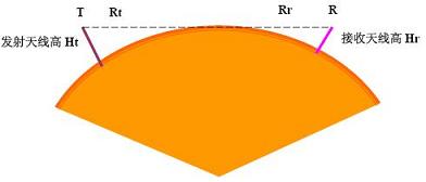
Considering the refraction effect of the atmosphere on radio waves, the limit direct viewing distance should be corrected as
Rmax = 4.12 {√HT
(m) + √HR (m)} (km)
Since the frequency of electromagnetic waves is much lower than the frequency of light waves, the effective direct viewing distance Re of radio wave propagation is about 70% of the limit direct viewing distance Rmax, that is
Re = 0.7 Rmax.
For example, HT and HR are 49 m and 1.7 m, respectively, then the effective direct viewing distance is Re = 24 km.
2.3 Propagation characteristics of radio waves on flat ground The radio waves directly emitted from the transmitting antenna to the receiving point are called direct waves; the radio waves emitted by the transmitting antenna directed to the ground and reflected by the ground to reach the receiving point are called reflected waves. Obviously, the signal at the receiving point should be a combination of direct wave and reflected wave. The synthesis of radio waves will not be simply algebraically added as 1 + 1 = 2, and the synthesis result will vary depending on the difference in the path length between the direct wave and the reflected wave. When the wave path difference is an odd multiple of half a wavelength, the direct wave and reflected wave signals are added together to synthesize the maximum; when the wave path difference is a multiple of a wavelength, the direct wave and reflected wave signals are subtracted and synthesized to the minimum. It can be seen that the presence of ground reflection makes the spatial distribution of signal strength quite complicated.
The actual measurement indicates that within a certain distance Ri, the signal strength will fluctuate as the distance or antenna height increases;
Outside a certain distance Ri, the signal strength will increase as the distance increases or the antenna height decreases. Monotonous decline. The theoretical calculation gives the relationship between Ri and antenna height HT and HR:
Ri = (4 HT HR) / l, where l is the wavelength.
It goes without saying that Ri must be less than the limit direct viewing distance Rmax.
2.4 Multipath propagation of radio waves In the ultrashort wave and microwave bands, radio waves will also encounter obstacles (such as buildings, tall buildings or hills, etc.) during the propagation process to reflect the radio waves. Therefore, there are many kinds of reflected waves that reach the receiving antenna (broadly speaking, ground reflected waves should also be included). This phenomenon is called multipath propagation.
Due to multipath transmission, the spatial distribution of the signal field strength becomes quite complicated, with large fluctuations. In some places, the signal field strength is strengthened, and in some places the signal field strength is weakened. Also due to the influence of multipath transmission, the radio wave The direction of polarization changes. In addition, different obstacles have different reflection capabilities for radio waves. For example, the reinforced concrete building has a stronger ability to reflect ultrashort waves and microwaves than brick walls. We should try our best to overcome the negative impact of the multipath transmission effect. This is precisely the reason why people often adopt space diversity technology or polarization diversity technology in communication networks with high communication quality requirements.
2.5 Diffraction Propagation of Radio Waves When a large obstacle is encountered in the propagation path, radio waves will propagate forward around the obstacle. This phenomenon is called diffraction of radio waves. Ultrashort waves and microwaves have higher frequencies, shorter wavelengths, and weak diffraction capabilities. The signal strength behind the tall buildings is small, forming a so-called "shadow zone."
The degree of signal quality is not only related to the height of the building, but also to the distance between the receiving antenna and the building, but also to the frequency. For example, there is a building with a height of 10 meters. At a distance of 200 meters behind the building, the received signal quality is almost unaffected, but at 100 meters, the received signal field strength is significantly weaker than when there is no building. Note that, as mentioned above, the degree of attenuation is also related to the frequency of the signal. For RF signals of 216 to 223 MHz, the received signal field strength is 16dB lower than when there is no building. For RF signals of 670 MHz, the received signal field The intensity is 20dB lower than when there is no building. If the height of the building is increased to 50 meters, the received signal field strength will be affected and weakened within 1000 meters from the building. In other words, the higher the frequency, the higher the building, the closer the receiving antenna and the building, the greater the impact on the signal strength and communication quality; on the contrary, the lower the frequency, the shorter the building, the farther the receiving antenna and the building , The smaller the impact.
Therefore, when selecting the base station site and setting up the antenna, you must consider the various adverse effects that may be produced by diffraction propagation, and pay attention to various factors that affect the diffraction propagation.
Basic knowledge of antenna (2)
Basic knowledge of antenna (2)