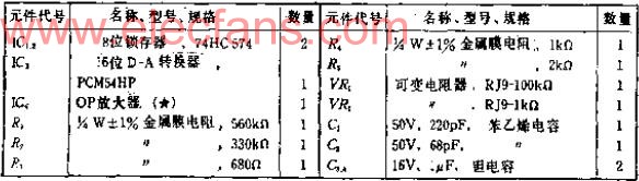
Circuit function The resolution of the 16-bit DA converter is 1/65535, which is equivalent to 0.0015% of the full-scale voltage, and 1LSB is the level of -96DB. So it can be used to generate high-precision waveforms or measure flow control. The 1LSB of 10V full scale is 152.6UV, which is close to the noise level, so the assembly problem should be considered when designing the circuit. Circuit working principle This circuit uses a cheap 16-bit DAC chip PCM54HP, this device is developed for digital audio equipment. Two zero 8-bit data latches are connected to the data input, and its function is to simultaneously input 16-bit data to reduce the noise caused by the time difference. If the DA conversion output does not require high-speed response, you can also remove the latch and add a low-pass filter at the converter output. PCM54 is basically the same as the ordinary voltage output DAC, and the output is a bipolar voltage of plus or minus 3 volts. In industrial applications, it is required to output plus or minus 5V or plus or minus 10V, so an amplifier A1 with an amplification factor of 3.3 is added to the output. The most significant bit should be controlled externally. Use R1, R2 and variable resistor DR1 to adjust linearity and monotonically increasing performance. The OP amplifier A1 can be selected according to the application. If it is used in a DC voltage generating circuit, a precision OP amplifier with small bias and small drift can be selected. For waveform generators or digital audio circuits, devices with good AC characteristics should be used. No offset adjustment circuit is added to this circuit, which can be added as needed. The cut-off frequency of capacitors C1 and C2 is 1MHZ. If it is used for DC, the cut-off frequency should be reduced. Selection of components The variable resistor VR1 of the most significant bit control circuit connects R1 and R2 in series to narrow the variable range. VR1 is a stable device, multi-turn type should be selected, all resistances are metal film resistances. Products with small temperature coefficients should be used. Adjustment Although zero adjustment or full-scale adjustment is very convenient, the adjustment of the most significant bit is more difficult. It is very troublesome to calibrate VR1, measure with a high-precision digital multimeter, and adjust 16 bits bit by bit in units of 1LSB. If a large number of converters need to be adjusted, you can connect the ROM with digital sine data to the input of this circuit, and use the hexadecimal counter to perform the address scan, so that you can generate a sine wave, adjust VR1, and make the distortion meter The indicated distortion is minimal. Assembly notes The 16-bit resolution DA or AD converter, because the voltage of 1 bit is very small, the grounding of the logic power supply and the analog power supply should be clearly separated. When digital data is used to generate a changing waveform at high speed, a good grounding should be performed to avoid The input data lead is coupled to the OP amplifier A1 peripheral lead or DAC summing point. This paper address: http: //TIcle/88/130/2010/20100507217195.html Din Cable,Pc Power Cable Harness,Audio Video Cable Assemblies,Pc Extension Wire Cable Dongguan City Yuanyue Electronics Co.Ltd , https://www.yyeconn.com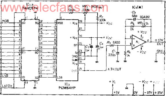
16-bit DA converter for audio to industrial use
16-bit DA converter for audio to industrial use