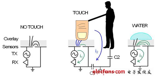
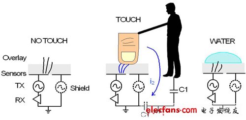
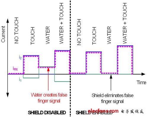
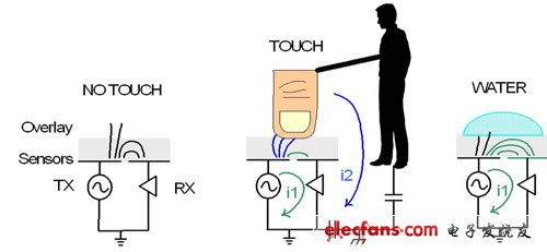
The waterproof function of the capacitive touch screen is expected to be greatly improved. Once the capacitive touch screen encounters moisture or liquid, the accuracy will be greatly reduced. Therefore, capacitive touch panels and controller developers are working together to combine the different functional characteristics of the self-capacitance and mutual capacitance sensing layers to improve the water resistance and wet finger tracking performance of capacitive touch screens. Two waterproof specifications, water resistance / wet finger tracking, are gaining importance There are many international standards for detailed definitions of waterproofing. Among them, the IEC-60529 standard of the International Electrotechnical Commission (InternaTIonal Electrotechnical Commission, IEC) defines the protection level (Ingress ProtecTIon, IP) in grades. 67, that is, it can withstand a lot of flying dust (dust-proof level 6), and can be immersed in water to a depth of 1 meter (water-proof level 7) without damage. However, few consumer mobile devices can meet this level, and the IP level has not yet been widely used in the product specifications of capacitive touch screens. Generally, the waterproof requirements of touch screens are based on user experience and product response when encountering moisture, rather than destructive testing. Although the definition of waterproofing has not been formally standardized, two waterproofing specifications that have been widely adopted by the industry are water resistance (Water RejecTIon) and support for wet finger tracking (Wet Finger Tracking). Water resistance, that is, when there is liquid on the touch screen, the system can eliminate false touch, and after removing the liquid, it can fully return to normal operation function. For example, if you accidentally spill coffee on your mobile phone, you will never want the mobile phone to automatically make a call or send a text message, even when you are in a hurry to clean up the phone, make any action, and expect the mobile phone to return to normal after drying Operating function. Water resistance is the most common and important condition factor for waterproofing, because the liquid must stay on the surface of the touch screen, and the touch screen must be able to return to normal without any false touch. However, water resistance cannot support touches on wet screen surfaces, which depends on wet finger tracking. The wet finger tracking function can track the position of the finger on a touch screen with moisture. Moisture on the surface of the touch screen will cause errors in the capacitance measurement, which will detract from the accuracy of the touch. The wet finger tracking function can ensure a precise value. In the presence of moisture, the allowable error is usually 1-2 mm. For critical functions such as making calls or sending e-mails, such an error is sufficient to meet operational requirements. The characteristics of the liquid are very important against water and wet finger tracking. A variety of liquid characteristics will form on the surface of the touch screen. One of them is water vapor condensation. In an environment with high humidity or rapid temperature changes, a thin layer of water vapor will condense on the surface of the touch screen. The second is water droplets, raindrops, sweat or any kind of liquid, dripping on the surface of the touch screen. The third is a thin water film. A large amount of water covers the entire surface of the touch screen to form a thin layer of liquid. As mentioned before, the spilled coffee belongs to this category. In addition, it is also important to recognize the size of the water droplets. Small water droplets usually refer to the size of the diameter measured after dropping onto the touch screen, and the size of the water droplets does not exceed 3 mm, while large water droplets are usually between 3-18 mm. The above three liquid types will produce different types of capacitance errors, and the touch screen controller must be able to respond. Even for the same type of liquid, self-capacitance sensing (Self-Cap) that does not support multi-touch and mutual capacitance sensing (Mutual Cap) that supports true multi-touch will produce different results. Some touch screen controllers will use these two technologies at the same time to solve the problems caused by the rejection of false touches caused by liquid detection. To understand these issues, you must first understand some basic physical changes that capacitive sensing produces when it encounters moisture. Use conductive shielding touch screen not to dance with moisture Capacitive sensing works because the human body itself is a conductor, and water containing impurities, such as tap water or coffee, is also a conductor, and will cause errors in capacitance measurement. Figure 1 is a simple self-capacitance physical model, electric field lines represent capacitance. Figure 1 Basic self-contained physical model The principle of self-capacitance is to detect the capacitance of a sensor to the ground of the circuit. The method is to apply an excitation signal to the sensor (TX), and then detect how much charge or current is used to contain the receiver (RX). Sensor is fully charged. In this model, there are two loops through which current may flow. One is direct coupling through the human body and the sensor (I2); the other is the formation of a marginal electric field coupling from the sensor to the adjacent sensor ( I1). The main signal source of self-capacitance is I2, mostly from direct capacitive coupling between the finger and the sensor (Figure 1). Direct capacitive coupling can be calculated using the parallel plate capacitance formula C = E0 & TImes; Er × A / d, where E0 is the permittivity of free space, Er is the relative permittivity of the touch screen protective layer, and A is the area covered by the finger, d is the distance between the finger and the sensor, with the touch screen protective layer material in between, and C1 and C2 in FIG. 1 are the capacitance of the mobile device and the human body relative to the ground, respectively. These capacitors are usually much higher than direct coupling capacitors, so all of these capacitors in series will reduce the direct coupling capacitance, however C1 is usually small enough to reduce the overall direct capacitive coupling, especially when the mobile device is completely battery-powered and there is no charger connected time. The marginal electric field signal I1 will increase some touch signals when touching, because the finger will absorb this signal and conduct it to the ground through the human body (added to I2). Moisture that has not been touched on the touch screen will have a great impact on I1, and these moistures are also the main source of errors in capacitive touch screens. Moisture will increase the margin between adjacent sensors The electric field, in turn, increases the capacitance. The thickness and permittivity of the protective layer of the end-view touch screen may cause sufficient capacitance change, such as a light touch of the finger, and let the sensing circuit misjudge it as a false touch. To solve this problem, you must use conductive shielding (sometimes called the Guard protective layer) (Figure 2). Figure 2 Basic self-contained physical model in shielded state Using the copied TX to drive the proximity sensor eliminates I1 and the sensing circuit does not detect any capacitance. However, in order to actually apply this solution, the touch screen controller must be able to switch the sensing pin flexibly, instantly switch between TX, RX and shield, and then sense the entire touch screen. On the traditional CapSense button, the shielding technology can also work the same. Figure 3 allows readers to understand how I1, I2 and the sensed current IRX vary with factors such as touch, moisture, and various changes in the shielded and unshielded states in different ways. The principle of mutual capacitance is to sense the capacitance between two sensors (Figure 4). Figure 3 Changes in self-capacitance current in different states and times Figure 4 Basic mutual-capacity physical model in shielded state Xinxiang Mina Import & Export Co., Ltd. , https://www.mina-motor.cn