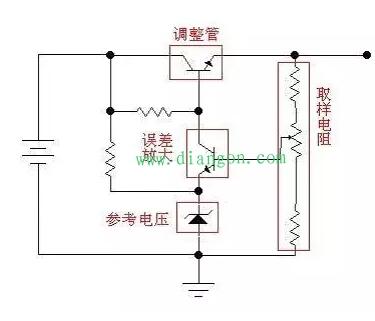
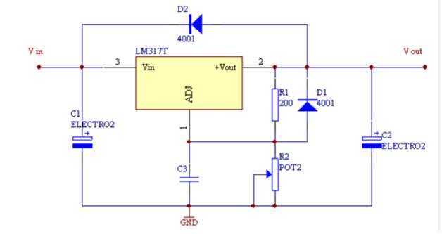
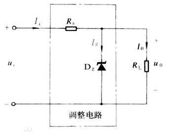
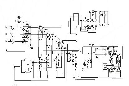
Stabilized voltage supply is an electronic device that can provide stable AC or DC power to the load, including AC regulated power supply and DC regulated power supply. When the grid voltage or load appears to fluctuate instantaneously, the regulated power supply compensates the voltage amplitude with a response speed of 10-30ms, which makes it stable within ±2%. As shown in the figure below, the variable resistor RW and the load resistor RL form a voltage divider circuit, and the output voltage is: Uo=Ui&TImes; RL/(RW+RL), so by adjusting the size of the RW, the output voltage can be changed. Note that in this equation, if we only look at the value change of the adjustable resistor RW, the output of Uo is not linear, but if we look at RW and RL together, it is linear. Also note that our diagram does not draw the leading end of the RW to the left and to the right. Although this is no different from the formula, but painted on the right, it just reflects the concept of "sampling" and "feedback"---the actual power supply, most of which are working in the sampling and feedback mode. In the following, there are few feedforward methods, or they are used, and they are just auxiliary methods. Let's continue: If we use a triode or FET instead of the variable resistor in the figure, and by detecting the magnitude of the output voltage, we can control the resistance of this "varistor" and keep the output voltage constant, so we will The purpose of voltage regulation is achieved. This triode or FET is used to adjust the voltage output, so it is called the adjustment tube. As shown in Figure 1, since the adjustment tube is connected in series between the power supply and the load, it is called a series-type regulated power supply. Correspondingly, there is a shunt regulated power supply, which is to adjust the output voltage by connecting the regulating tube in parallel with the load. The typical reference regulator TL431 is a shunt regulator. The so-called parallel means that, like the Zener tube in Figure 2, the shunting is used to ensure the "stability" of the emitter voltage of the attenuation amplifier. Perhaps this figure does not let you see that it is "parallel" at once, but Take a closer look, it is true. However, everyone should also pay attention here: the Zener here works with its non-linear region, so if it is considered a power supply, it is also a nonlinear power supply. In order to facilitate everyone's understanding, we look back at a suitable map, until we can understand it concisely. Since the adjustment tube is equivalent to a resistor, the current will flow when the current flows through the resistor, so the adjustment tube operating in a linear state generally generates a large amount of heat, resulting in inefficiency. This is one of the main drawbacks of linear regulated power supplies. For a more detailed understanding of linear regulated power supplies, please refer to Analog Electronic Circuit Textbooks. Here we mainly help you to clarify these concepts and the relationship between them. figure 1 Generally speaking, the linear regulated power supply is composed of several basic parts such as an adjustment tube, a reference voltage, a sampling circuit, and an error amplifying circuit. It may also include some parts such as protection circuits, startup circuits, and the like. The following figure is a simple schematic diagram of a linear regulated power supply (schematic diagram, omitting components such as filter capacitors). The sampling resistor samples the output voltage and compares it with the reference voltage. The comparison result is amplified by the error amplifier circuit and the control tube is controlled. The degree of conduction keeps the output voltage stable. figure 2 Linear DC stabilized power supply circuit diagram As shown in the figure, a typical linear DC stabilized power supply circuit diagram consists of a power switch K, a fuse, an AC-DC adapter, an integrated regulator, and a post-stage filter. When 220V AC is input and the switch K is closed, a stable DC voltage is output, and the stable output is not affected by the fluctuation of the 220V AC grid and the weight of the electronic circuit within a certain range. The function of the rectifier is to convert the reduced power frequency AC voltage into a DC voltage. Figure 1.25 shows how the rectifier works. In the positive half of the alternating current, the secondary of the transformer is negative, and the current flows from the positive pole to the negative pole of the transformer through D1, load and D3. Thus, if the conduction voltage of the diode is ignored, a size equal to that of the transformer secondary is obtained on the load. The voltage waveform has a polarity of positive and negative. In the negative half cycle of the alternating current, the secondary of the transformer is negative and positive. The current flows from the positive pole to the negative pole of the transformer through D2, load and D4, so that the load also gets a size and transformer. The same voltage waveform of the same level, the polarity is the same as the positive half cycle, and it is also positive and negative. Therefore, under the action of the positive and negative half cycles of the AC signal, the rectifier outputs a unipolar ripple voltage, and the DC component of the output is greater than zero. The circuit output voltage of Figure (a) is regulated by potentiometer Rp and has a linear regulation characteristic. The figure above shows a simple voltage regulator circuit consisting of a current limiting resistor Rs and a Zener diode Dz. The switching regulator circuit has the characteristics of small size and high efficiency. The efficiency of the linear power supply is 30% to 55% of the voltage regulator circuit; the switching regulator can reach 60% to 85%, and the power frequency transformer and the huge heat sink can be omitted, and the volume and weight are greatly reduced. Such circuits have found wide application in various electronic devices. A commonly used method for implementing switching control; a self-excited switching regulator, a pulse width modulation switching regulator, and a DC conversion switching regulator. The figure above is a block diagram of a switching regulator circuit using a DC converter. The DC voltage obtained by directly rectifying-filtering the power frequency voltage is changed from a switching transistor to a high frequency voltage. The latter is converted to a certain voltage by a high-frequency converter transformer, and then subjected to high-frequency rectification-filtering to give a desired output voltage u0; the operation of the switching transistor is controlled by a pulse modulator and a driver amplifier. When the output voltage u0 changes, the sampling signal from the output terminal generates an error signal through the comparison circuit, and then controls the switching ratio of the switching tube through the pulse modulator, thereby keeping the output of the DC converter stable. The switch tube is intermittently operated in the saturation region, so the power consumption is smaller than that of the linear power supply, so the efficiency is high. The high-power power regulator of the voltage regulator circuit is composed of a compensation transformer, a voltage regulator, a control circuit, a detection circuit and an operation circuit. A triode is connected in series between the input DC voltage and the load, and the voltage drop of the triode tube is replaced by the voltage drop of the triode tube. when
Tobacco control has been a common global concern, while the traditional tobacco industry gradually, new tobacco has become the new strategic layout of tobacco giants. In this context, the emergence of e-cigarettes has further led to the replacement of traditional tobacco. At present, there are already a thousand different types of e-cigarettes, which have undergone several stages of development. The e-cigarette we are introducing today is the CBD pod systewm, a new type of e-cigarette. In this article we will combine the characteristics of the CBD with a brief analysis of it.
·Anti-anxiety
According to scientific studies,CBD can help depressed patients reduce their anxiety. The use of CBD can help maintain endogenous cannabinoids at a reasonable level, making the patient feel good and happy physically, and without any dependence.
·Anti-ageing
CBD is very powerful in anti-ageing. As a non-psychoactive component of the cannabis plant CBD inhibits the glutamate toxic response of cortical neurons and suppresses excessive oxidative stress, helping the body to achieve anti-ageing effects.
·Anti-inflammatory
CBD reduces the free radicals that cause neurodegenerative diseases and reduces swelling through its anti-inflammatory effects. In addition, CBD stimulates appetite and relieves pain.
China Disposble Vape Pen,E-Cigarette Cbd Vaporizer,Best Disposable Cbd Vape Pen,Disposable Cbd Vape Shenzhen MASON VAP Technology Co., Ltd. , https://www.disposablevapepenfactory.com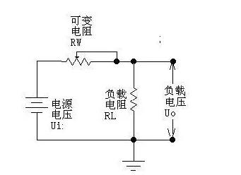
![]() or
or ![]() Change causes output voltage
Change causes output voltage ![]() When changing,
When changing, ![]() The change will be reflected to the emitter junction voltage of the transistor
The change will be reflected to the emitter junction voltage of the transistor ![]() On
On ![]() Change, thereby adjusting
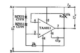
Change, thereby adjusting ![]() To keep the output voltage substantially stable. According to the role played by the triode, it is called the adjustment tube. Since the adjustment tube and the load are in series, Figure 15-2-1 is called a series regulator circuit. It consists mainly of a reference voltage, a comparison amplifier, a sampling circuit, and an adjustment component. The comparison amplification can be a single tube amplification circuit, a differential amplification circuit, or an integrated operational amplifier. The adjusting component can be a single power tube, the composite tube or several power tubes connected in parallel, and the sampling circuit takes out the output voltage
To keep the output voltage substantially stable. According to the role played by the triode, it is called the adjustment tube. Since the adjustment tube and the load are in series, Figure 15-2-1 is called a series regulator circuit. It consists mainly of a reference voltage, a comparison amplifier, a sampling circuit, and an adjustment component. The comparison amplification can be a single tube amplification circuit, a differential amplification circuit, or an integrated operational amplifier. The adjusting component can be a single power tube, the composite tube or several power tubes connected in parallel, and the sampling circuit takes out the output voltage ![]() A part of it is compared with the reference voltage VREF.
A part of it is compared with the reference voltage VREF.