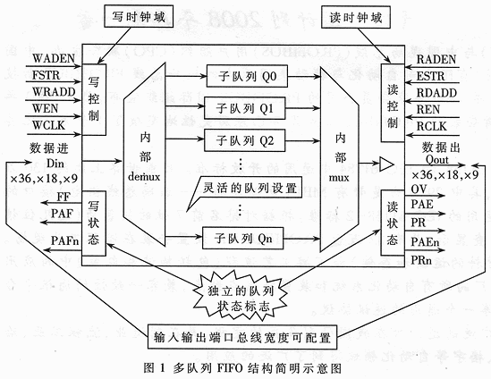
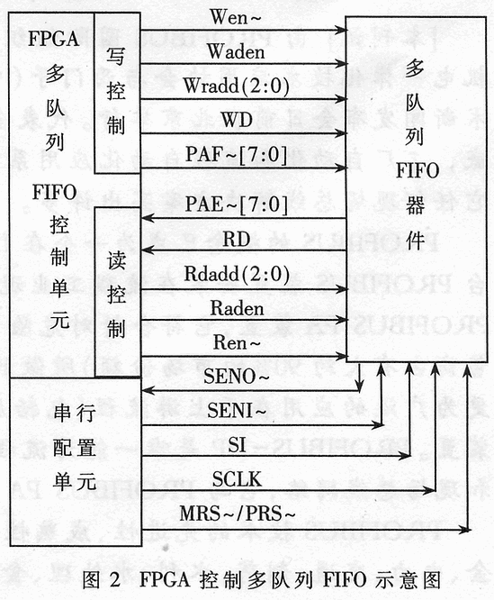
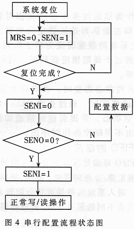
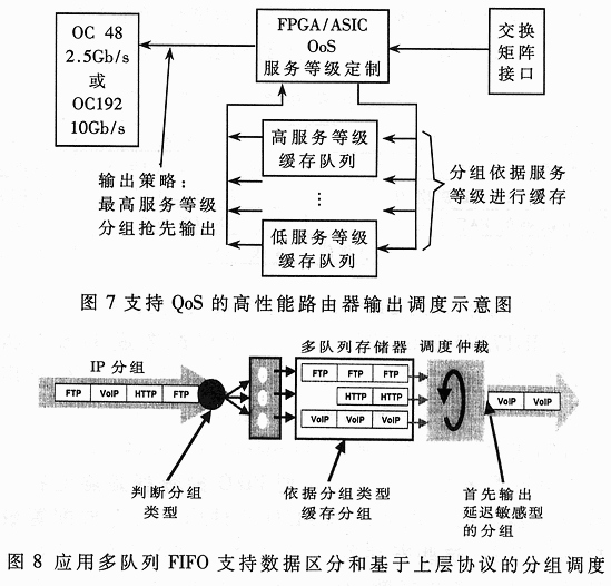
Abstract: Supporting QoS in IP networks is a hot topic in recent years, and IDT's new storage device, multi-queue FIFO, can support QoS applications. Because it has multiple queues that can be configured under a single device and has a high degree of flexibility for cascading, the device has a good application prospect in supporting data-differentiated caching and processing. The main characteristics of multi-queue FIFO are introduced, and the FPGA control method and its application to support QoS scheduling in the router are given. Supporting QoS (Quality of Service) in IP networks, in addition to the development and improvement of related network protocols, also requires the router to provide differentiated services for different types of packets or data streams. Multi-queue FIFO is the industry's first new memory device introduced by IDT in 2002, which can effectively support the high-speed implementation of QoS. The chip is designed to improve network service quality and other applications that require reordering of queue data. It supports flexible data differentiation applications while avoiding complex off-chip control logic. This paper introduces the basic characteristics of the device and the FPGA control method, and gives the application of the memory to support QoS scheduling in the router. The device is equipped with an embedded FIFO memory core and high-speed queue logic for high data transfer bandwidth and flexible configurability. The device supports up to 7.2Gbps sustained transfer rate and supports up to 32 sub-queues on a single chip. The device cascade supports up to 256 sub-queues. Only one FIFO can buffer multiple data streams, which helps users select different queues to perform independent reading and writing functions. The multi-queue FIFO not only provides traditional FIFO functions such as data buffering, queue full-empty status indication, write/read clock independence, and write/read bus matching, but also supports packet mode and data discrimination queuing, thus eliminating Previously, expensive and complex operational logic was used to implement similar functions. A schematic diagram of a multi-queue FIFO is shown in FIG. As can be seen visually, the multi-queue FIFO is a memory that provides a distinguishable plurality of logical sub-queues within a single physical device. Differentiated means that each sub-queue can be independently written/read, and each sub-queue has an independent status indication. FPGA control of multi-queue FIFO is reflected in three aspects: configuration, write operation and read operation, as shown in Figure 2. 2.1 Multi-queue FIFO configuration The new IDT multi-queue flow control device provides system designers with the latest solutions that enable selectable, differentiated sequential data access operations with a single highly integrated device. This flexible feature can be implemented with a range of device setup options. Unlike previous single-queue FIFO devices (such as the IDT 3690), multi-queue FIFOs have relatively complex configurability. In addition to the write/read port bus width, which can be directly set by the chip pins, there are two configurations. Mode: Default configuration and serial configuration, where serial configuration, also known as user-defined configuration, is a new device feature. The user has a great deal of flexibility in the configuration of the multi-queue FIFO. For example, IDT72V51336~IDT72V51356 can be configured as 1-8 queues, and the depth settings of each queue are independent of each other. The flag bits are user programmable and each subqueue is independent. Configuration can be done through a dedicated serial programming port, or the default mode can be used if programming is not required. Serial configuration means that the data configuring the multi-queue FIFO is serially serialized into the device. Inside the multi-queue FIFO device are registers for storing configuration data, which are in 18-bit units. Let Q be the number of subqueues configured by the device. Qmax is the maximum number of subqueues supported by the device. There are (Qmax & TImes; 4+1) registers in the device. The amount of bit data Sum required for a single device configuration is: 18+Qx72+1. The last bit is the configuration end indication. If Q=8 in the design, then Sum=19+8x72=595 bits. The specific configuration of the configuration data can be found in the IDT document AN-303 (DSC-5997/2, July 2003 version). The serial configuration signal timing (single device) is shown in Figure 3. If multiple devices are cascaded, SO and SENO~ of device i should be connected to SI and SENI~ of device i+l, respectively, and SENO~ of the cascaded tail device should be detected to determine whether the entire configuration is over. When writing a serial configuration program in hardware description language, you should refer to the serial configuration flow state diagram shown in Figure 4. The “configuration data†in the figure can be stored either in the on-chip RAM of the FPGA or in off-chip memory. Since the amount of configuration data is small, it is recommended to store it in on-chip RAM because this eliminates the interconnection with off-chip memory. 2.2 Write operation The multi-queue FIFO uses the queue address Wradd/Rdadd to distinguish between individual write/read subqueues, and the new write/read subqueue is specified with the high level of the lock valid signal Waden/Raden, and the write/read enable is Wen/Ren. The multi-queue FIFO write operation has a postponed effect compared to the write queue address switch, that is, the data sent to the write sub-queue on the bus is the second write clock cycle after the new sub-queue address is locked. If this timing feature can be utilized to lock the new sub-queue address two cycles ahead, then 100% of the write bus cycle can be used. When the subqueue full indicates that FF is valid, new data cannot be written to the queue, and data loss occurs. Generally, in order to avoid this situation, the PAF offset value must be configured. After seeing that PAFn~ is low, the write operation is stopped. Figure 5 shows the timing diagram for the uninterrupted write operation. A read operation similar to a write operation also has a delay effect relative to the read queue address, that is, the data presented on the read bus is converted to data in the new sub-queue during the third read clock cycle after the new queue address is locked. So if you can lock the new queue three times in advance, you can achieve 100% read bus utilization. When the selected queue state is empty, the read port is full high. After the PAE offset value is configured, you can know the empty or non-empty status of the queue by looking at PAEn~, and read or switch the new queue in advance. Figure 6 shows the timing diagram for the uninterrupted read operation. The multi-queue FIFO can meet the requirements of the device to achieve quality of service, packet priority and multi-stream aggregation/separation. For example, based on packet client prioritization, data entering the system can be assigned to one of multiple queues, each representing a different level of service. The processor first processes the packets with higher priority according to certain algorithms to ensure the service level of the entire network. The author uses a multi-queue FIFO to implement multi-priority scheduling in the backbone router switching network. The specific example is shown in Figure 7. The division of service levels typically gives high priority to delay-sensitive packets depending on the type of packet. Different from the traditional first-come-first-served service (FCFS), differentiated services can provide certain network service quality. Figure 8 is a concrete example. If you do not apply multi-queue FIFO, it is necessary to use SRAM to simulate multiple queues, you have to add a lot of complicated control logic, consume processor resources, or use multiple independent storage devices to queue different types of packets, which increases the actual Board (PCB) is difficult and has poor scalability. 
1 multi-queue FIFO introduction 
2 multi-queue FIFO FPGA control
image 3
The configurable items of the multi-queue FIFO are: (a) the number of logical subqueues within the device; (b) the storage depth of each subqueue; (c) the PAF (almost full) offset value of each subqueue; (d) each sub-queue The PAE (almost empty) offset value of the queue (valid in normal mode, converted to full packet indication PR in whole packet mode). 
Figure 5
2.3 read operation
Figure 6
3 multi-queue FIFO application 
In addition, in the case of continuous power continuous operation, the FPGA can control the multi-queue FIFO configuration to be changed at different time intervals to suit different application needs. For example, to adapt to different types of data, it can be serially configured into corresponding multiple sub-queues during temporary storage; and only the same type of data can be configured to be used in a single queue. Therefore, the multi-queue FIFO application has high flexibility and good prospects.